

Forged Pistons 09/18/99
Having determined that the factory cast pistons might not be up to the task of sustained boost, it was decided to replace them with forged pistons. Forged pistons have several advantages over cast pistons. The dense grain structure and flow direction makes them 3 to 4 times stronger than a cast piston and also allows them to dissipate heat 2 to 3 times faster. The 2618-T61 alloy used has a much higher tensile strength than the cast piston material and has a relatively low expansion rate so that these pistons can be fitted at a relatively tight .0035 clearance.
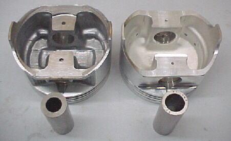
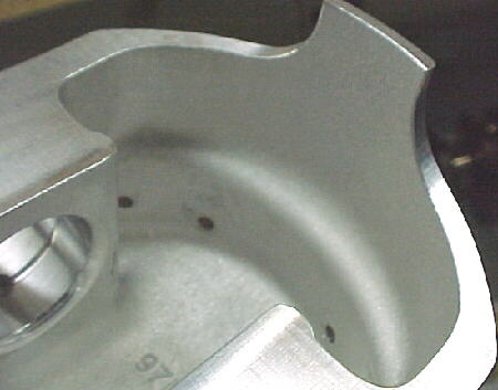
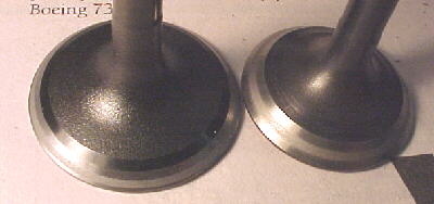
I contracted JE Pistons in Huntington Beach, California to make a custom set of forged pistons to my specs. JE did a wonderful job and delivered the parts ahead of schedule. I wanted to retain the same compression ratio as the naturally aspirated pistons, even with the turbo, as this engine will run exclusively on 100LL. The higher compression ratio gives higher hp for the same boost and lower fuel flows due to higher thermal efficiency. I added additional squish area on the other side of the piston to match that on the head casting. The dish and valve reliefs were made slightly deeper to hold the CR the same. Both the stock piston and the forged piston measured 14.5cc of dish volume. The turbo piston by comparison has a 28cc dish. Calculated CR is 9.45 to 1 on the new pistons.
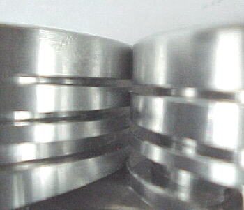
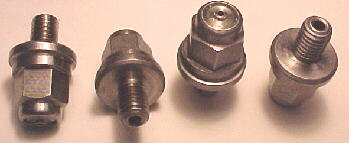
Stock atmo piston left, JE forged piston right
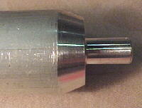
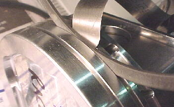
Note pin wall thickness
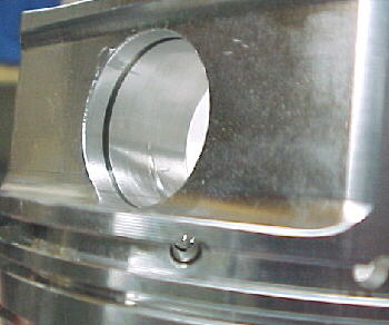
I selected JE's tool steel wrist pins which are 20 grams lighter yet stronger than the factory pins. Pin oiling was specified to be pressure fed from the oil ring groove. JE added a nice chamfered groove to disperse the oil film better. A nice touch.
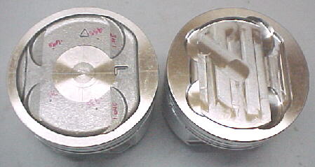
The top ring groove was spaced down more and the 2nd ring land was made much thicker, thus stiffer. This is very heavily loaded on a turbocharged engine. The thicker sections also help dissipate heat more quickly which reduces dome temperatures and protect the top ring from excessive temperatures as well.
The design of a forged piston permits more area between the upper and lower portions to increase heat transfer. Heat transfer rate is an important consideration on a turbo engine as the cooler the alloy can run, the stronger it remains and the higher the hp or heat flux that can be maintained without failure.
The piston and pin assembly weighed 10 grams less than the stock piston and the bore was increased .1mm so the cylinders must be bored slightly to establish the correct clearance.
The block was machine bored for .0035 wall to skirt clearance.
Valves and seats were refaced. Seat widths were increased slightly over stock for better heat transfer. All valves were returned to their original position. Note markings on chamber.
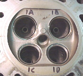
Seat contact was checked by hand lapping the valves. Note contact on valve face. Intake left .050 wide, upper 3/4 of face. Exhaust right .070 wide, middle of face. This is how a properly performed valve job should look.
I machined up a tool to properly install the valve stem seals. These should be pressed on by hand. Note brown seals for exhaust stems, black for intakes.
Heads were thoroughly washed in hot, soapy water, then lacquer thinner to remove all dirt. Valve stems were coated with Mobil 1 oil and installed into heads. New valve keepers were included in the excellent Subaru gasket set. These take a lot of fiddling to install with grease and some dental tweezers.
The pistons weighed within .9 grams from JE and the factory rods were within 2 grams. The heaviest rod was placed with the lightest piston to get total reciprocating masses as close as possible. This allowed a tolerance of 1.3 grams between lightest and heaviest assembly to be achieved.
Rings were checked for end gap, groove depth and side clearance. Top ring end gap was set a .014 which is more than the factory suggested .008 to .010 which was felt was too tight for this application. Second ring gap was set at .014 also compared the factory tolerance of .014 to .020. Side clearance was .002.
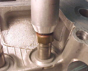
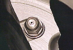
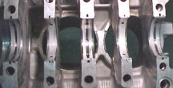
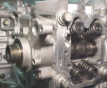
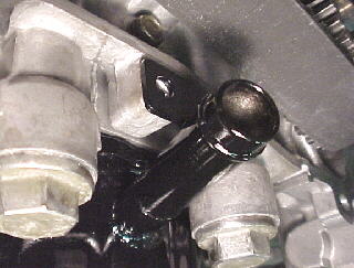
The EJ22 turbo has piston oil jets to cool the piston domes. These are nicely made with a spring loaded ball valve internally to retain oil pressure at low rpm. As oil pressure and rpm build, the jets open up. Very clever.
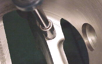
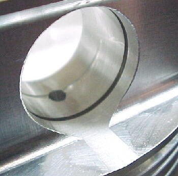
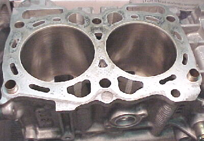
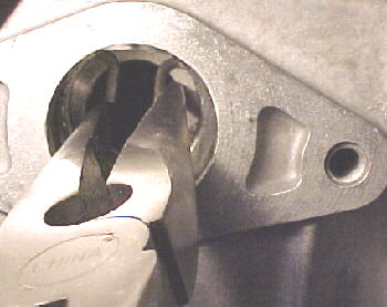
Note holes in cylinder wall to permit piston pin installation
The main bearings were installed into their original locations as they were in mint condition as were the rod bearings.
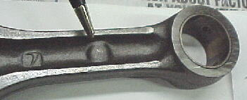
Bearings were lubed with Mobil 1. The rods were assembled onto the crankshaft. Note the bumps on the rod column face the harmonic balancer. Bolts were torqued to 34 ft./lbs. Rod eyes were lubed prior to case assembly.
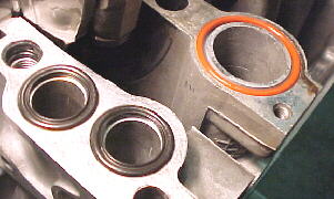
The crank is lowered into the right case halve by holding the #2 and #4 rod eyes. RTV sealing compound is put on the case joints and water and the four oil sealing O-rings are put into their counterbores on the right case halve. It takes a strong hand to hold the left case halve and hold #1 and #3 rods vertical while lowering the left case halve onto the right.
The smaller case bolts were snugged up. New sealing washers for the 6 wet main case bolts were lubed up and slid on. All case bolts were then torqued up.
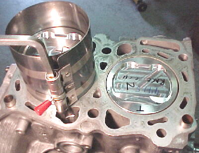
Pins are installed through the holes in the block and cylinder walls. Lining up the piston pin bores with the rod eyes is time consuming and lots of fun. Be patient.
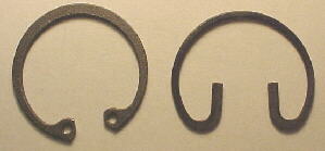
The Tru-arc pin circlips from JE could not be installed as expected due to the strange Subaru pin installation method. The Tru-arcs were also too big to be fully compressed while going into the pin boss bore. The factory gasket set provided 8 new wire type circlips which were flattened on a belt sander to .044 thickness to fit into the JE piston pin grooves. This worked very well. Note that Spirilox and Tru-arc pin locks will be virtually impossible to install on the EJ22. You must use wire locks.
10/02/99
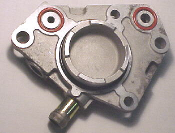
The heads were torqued into place using the very strange recommended sequence. The camshafts were installed into the heads with Moly anti scuff grease on the lobes. The left front cam housing and turbo oil/water supply plate on the right rear head were also installed. Note silicone O-rings on housing to seal water and oil passages.
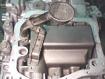
The windage tray and oil pickup were bolted down. Note that another O-ring seals the pickup tube.
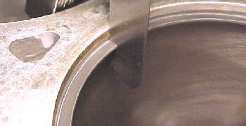
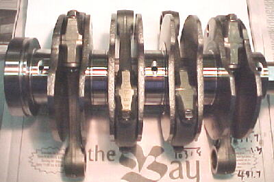
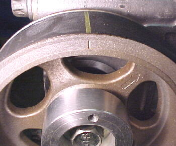
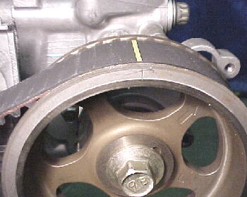
The crank keyway position at TDC #1 is 90 degrees to the right. The crank is not set at TDC #1 as you would think to install the belt. There is a small notch on one of the reluctor tabs on the crank sprocket which should line up with the case parting line, vertically upwards. The crank keyway will be facing vertically downwards. Subaru does mark their belts with yellow lines as shown below. Both cam pulleys are aligned with their marks facing vertically upwards as will be the crank sprocket mark.
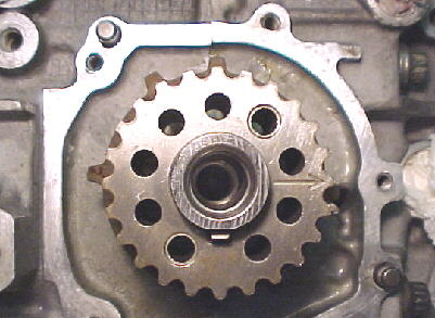
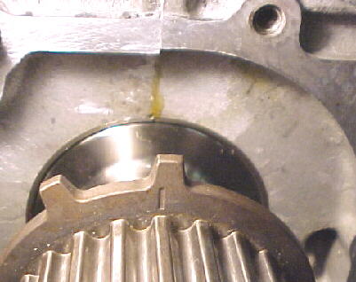
Crankshaft alignment mark for installing cam belt
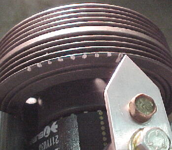
As I eliminated the plastic cams covers to reduce weight and increase accessibility to the drive components, I eliminated the factory ignition timing marks. I fabbed a nice aluminum pointer and bolted it to the crank sensor mount and degreed the crank pulley in 5 degree increments, out to 40 degrees.
The turbocharger oil drain was machined out of a piece of 3/4 inch steel bar stock to take 5/8 ID silicone hose. A barb was machined into the drain for hose retention. A unibit was used to drill a nice hole in the pan. The drain was TIG welded into the pan an another tab was welded onto the drain to allow bolting to the rear cover for extra strength.
Rocker shafts were torqued down and valve covers installed. Subaru uses some very nice shouldered bolts and O-rings to hold the VCs down to prevent squished out gaskets. The gaskets are top quality neoprene, spigoted into cast grooves. No chance of leakage here.
The new factory oil pan was installed using the same Permatex Ultra Grey RTV sealing compound employed on the rest of the engine. This is excellent stuff without the acetic acid smell of conventional silicones.
10/23/99 Final Assembly
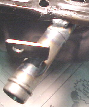
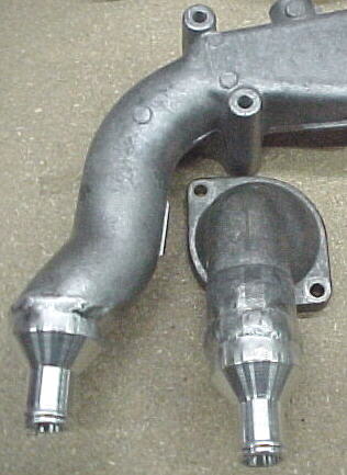
I machined some water adapters from 6061 T6 bar stock to reduce the size of the main water connections from 1 1/2 inches down to 3/4 inches as this will be the size of hose run in the main cooling system and radiator. These were TIG welded to the water manifold on top of the block and the thermostat housing.
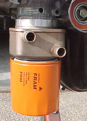
The Modine water to oil, oil cooler and filter assembly was screwed together using a shorter Fram PH43 filter for radiator clearance which is planned to be fitted under the oil pan.
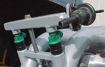
The fuel rails, regulator and Bosch 390cc/min. injectors were fitted to the intake manifold.
The alternator, vacuum pump, intake manifold and turbocharger mounts were bolted up.
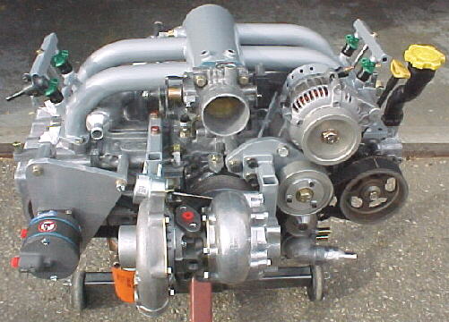

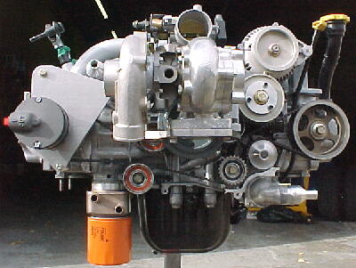
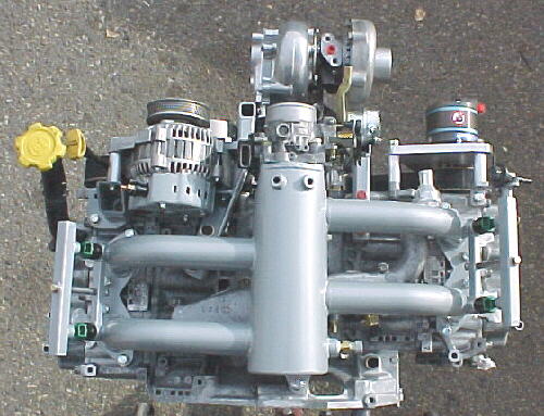
This pretty much ends the engine assembly until it is hung in the airframe to build the throttle linkage, intercooler system and exhaust system.