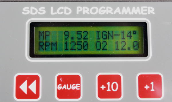
Gauge 4 screen showing important parameters, including AFR


Basic SDS Tuning Guidelines for Aircraft Applications
This article is intended to be used in conjunction with the SDS Installation and Tuning Manuals which contain more detail. You should first become familiar with all the different programmable parameters by reading the main and supplemental manuals, available here: http://www.sdsefi.com/program.html
The primary focus of this article is to make people aware of the general process of tuning the fuel delivery and spark timing for Lycoming engines.
Background Technical Information
Air/ fuel Ratio
In most spark ignition, internal combustion engines, the mixture is combustible within an AFR (air/fuel ratio) range of roughly 9 to 1 to about 17 to 1. 9 being very rich, 17 being very lean. 14.7 is the stoichiometric ratio (chemically correct) for lowest emissions. Best power is obtained at around 12.5 for most naturally aspirated engines.
Detonation
The fuel/air mixture normally burns at a uniform rate within the combustion chamber however if the rate of pressure or temperature rise becomes excessive, detonation can occur. This is the spontaneous explosion of the remaining mixture sometime after the spark event occurs. The result is a rapid and excessive pressure and temperature rise within the chamber, which can often lead to broken ring lands on the piston. Some engines can withstand light or moderate detonation for many hours, some can't. Heavy detonation is like hammer blows on top of the piston and most engines won't take this for more than a few seconds at a time under heavy detonation. Having the ignition timing too far advanced for the fuel octane is the leading cause of detonation, running the AFR too lean also contributes to detonation. You are not likely to be able to hear detonation over the noise of the propeller and exhaust in an airplane so we must program the ECU so that detonation cannot occur in the first place.
Pre-ignition
This happens when there is a hot spot somewhere within the cylinder which raises the temperature of the mixture above its autoignition temperature. This happens before the spark is initiated, leading to a massive temperature and pressure rise before the piston reaches TDC . Most of the heat and excess pressure goes into the piston. Within the space of a few seconds, the piston will simply melt in the middle, the pressure caving in the crown and melting the spark plug electrode off. You cannot hear pre-ignition at all and failure is virtually instantaneous in all cases.
Now that the scary stuff has been discussed, we can get into the meat of proper ECU programming to try to prevent these things.
Magnet Position Value
First item to check is the magnet position value. Read the appropriate section in the SDS F Supplement Manual to fully understand this. Basically, this is a one time calibration to the ECU to correct displayed ignition timing with actual ignition timing on the engine. You must connect a timing light to the #1 plug or coil wire and have a mark on the crank pulley for TDC or 10 degrees BTDC. in some cases, you can try the inductive clip on the coil trigger wire, red positice coil wire or black ground coil wire. Use a dumb timing gun without an adjustable knob on it. (important)
If you only have a TDC mark, set the rpm ignition timing in the programmer to 0 at 750, 1000 and 1250 rpm. If you have a 10 degree BTDC mark, set the rpm ignition timing to 10 at these three rpm ranges. Start the engine (mindful of the propeller!) And set the throttle to get an idle at 1000 rpm, confirm in gauge 1 mode. Scroll right until you get to the Magnet Position Parameter. The default value is 80 for magnet position. Check your timing mark with the gun. If your timing is the same as what you have set in the ECU, no adjustment to Magnet Position is required. If the timing does not agree, change the setting by using the +1 or -1 buttons to increment or decrement the 80 value until actual timing matches your programmer timing value at 1000 rpm. A change of 1 will change ignition timing 1 degree. Once Magnet Position is set, whatever you enter for rpm ignition timing will be correct as long as you don't move the Hall sensor. You may now reset your rpm timing values to whatever you desire.
If you don't verify that the magnet position is correct, you really don't know if your actual ignition timing is correct so you could have more advanced timing than you think, which can lead to detonation.
Ignition Mapping
On most Lycoming engines, best power is made at around 24-26 degrees BTDC at sea level, assuming no detonation is present. Typically, ignition timing starts out on most engines at about 10 degrees BTDC from 500 to 1000 rpm and we'd increase timing about 5 degrees per 250 rpm step in the programmer until you reach 24-26 at 2000 rpm. The timing would stay at 25 degrees above this rpm all the way up to redline when you are operating on 100LL. We've found that timing should be limited to no more than 24 degrees when running on 91 octane mogas so that detonation is less likely to occur and we may retard timing further at high manifold pressures to stop detonation. Timing values would be also adjusted downwards as compression ratios are taken above 8.5 to 1.
On the SDS, we have two parameters affecting ignition timing- RPM IGNITION and IGN RET- ADV/ LOAD. Total timing is the composite of these two figures- RPM timing plus or minus the MAP retard or advance value. For simplicity on naturally aspirated engines, we usually just use the RPM IGNITION values. It's possible for advanced users to also use the IGN RET- ADV/ LOAD parameter to advance timing at low manifold pressures (MAP) and retard it at high MAP to possibly obtain higher cruise efficiency. On naturally aspirated engines, IGN RET- ADV/ LOAD values can all be set to 0 so they don't affect total timing and make things easier to understand.
Typical timing on Lycoming engines can look something like this on 91 octane fuel with compression ratios of 8.5 to 1 or less:
RPM Timing Value
500 10
750 10
1000 10
1250 15
1500 20
1750 24
2000 24
2250 24
2500 24
2750 24
MAP IGN RET- ADV/ LOAD Value
1.12 0
1.59 0
2.06 0
2.53 0
3.00 0
3.47 0
3.94 0
4.41 0
4.88 0
5.35 0
5.82 0
6.29 0
6.76 0
7.23 0
7.70 0
8.17 0
8.64 0
9.14 0
9.58 0
10.0 0
10.5 0
10.9 0
11.5 0
11.9 0
12.4 0
12.8 3A
13.3 3A
13.8 3A
14.3 3A
14.8 3A
15.2 3A
15.7 3A
16.2 3A
16.6 3A
17.1 3A
17.6 3A
18.0 3A
18.5 3A
19.0 3A
19.4 3A
19.9 3A
20.4 2A
20.9 2A
21.3 2A
21.8 2A
22.3 1A
22.7 1A
23.2 1A
23.7 0
24.1 0
24.6 0
25.1 0
25.6 1R
26.0 1R
26.5 2R
27.0 2R
27.4 2R
27.9 3R
28.4 3R
28.8 3R
29.3 4R
29.8 4R
30.3 4R
30.7 4R
On 100LL, typical timing might look like this.
RPM Timing Value
500 10
750 10
1000 10
1250 15
1500 20
1750 26
2000 27
2250 28
2500 29
2750 29
MAP IGN RET- ADV/ LOAD Value
1.12 0
1.59 0
2.06 0
2.53 0
3.00 0
3.47 0
3.94 0
4.41 0
4.88 0
5.35 0
5.82 0
6.29 0
6.76 0
7.23 0
7.70 0
8.17 0
8.64 0
9.14 0
9.58 0
10.0 0
10.5 0
10.9 0
11.5 0
11.9 0
12.4 0
12.8 3A
13.3 3A
13.8 3A
14.3 3A
14.8 3A
15.2 3A
15.7 3A
16.2 3A
16.6 3A
17.1 3A
17.6 3A
18.0 3A
18.5 3A
19.0 3A
19.4 3A
19.9 3A
20.4 2A
20.9 2A
21.3 2A
21.8 2A
22.3 1A
22.7 1A
23.2 1A
23.7 0
24.1 0
24.6 0
25.1 0
25.6 1R
26.0 1R
26.5 2R
27.0 2R
27.4 2R
27.9 3R
28.4 3R
28.8 3R
29.3 4R
29.8 4R
30.3 4R
30.7 4R
Fuel Mapping
You need to have a wideband AFR monitor installed to display and verify AFRs. Most mapping can be done with the aircraft chocked, brakes on and tied to a vehicle on the ground. Take suitable precautions when ground running at high power settings and watch oil and CHTs, don't exceed limits here.
RPM Fuel Values
Our goal is simply to adjust the RPM FUEL parameter at each 250 rpm break point to obtain an AFR of around 12.0 to 12.5 up to 1500 rpm (idle and taxi range) and 11 to 11.5 above 1500 rpm. Get on the brakes and start the engine. Don't do any programming to RPM Fuel values until the engine reaches at least 150F engine/ cylinder head temperature. At each rpm, verify it's stabilized at each rpm break point in the SDS programmer (not the aircraft tach), check AFR, increment or decrement the RPM FUEL value using the +1 or -1 buttons until you get the desired AFR. Making the RPM FUEL value larger makes the AFR richer and vice versa. Note there will be some scatter in the readings so aim for a nominal reading. If you are trying to get 11.0, it's somewhat normal to see variations between about 10.8 to 11.2.
Keep increasing the throttle to increase rpm, stabilize and verify at each 250 rpm break point, check AFR, correct the RPM FUEL value to get desired AFR. Repeat. Go all the way up the rev range until you are at full throttle. You are done on the ground now, assuming the engine starts and warms up smoothly. If not, consult the manual on how to change the START and ENGINE TEMP parameters to get good hot and cold starting and warmup.
This parameter compensates for volumetric efficiency changes with rpm. Typical O-360 tables using 60lb./ hr. injectors might look something like this:
500 155
750 156
1000 166
1250 170
1500 170
1750 170
2000 165
2250 165
2500 170
2750 175
Be aware that injector size directly affects the RPM Fuel value. Smaller injectors require larger RPM Fuel values and vice versa.
Once the engine is warmed up, AFRs are a composite of RPM FUEL values X MAP FUEL values with small corrections for intake air temperature. Since MAP values are usually a linear progression, we usually don't have to touch those values on naturally aspirated engines and most programming is done only on the RPM FUEL values. You should check your MAP values however and they should look something like the figures below:
MAP Values
MAP Value
1.12 100
1.59 100
2.06 100
2.53 10
3.00 11
3.47 12
3.94 13
4.41 14
4.88 15
5.35 16
5.82 18
6.29 20
6.76 22
7.23 24
7.70 26
8.17 28
8.64 30
9.14 30
9.58 30
10.0 30
10.5 30
10.9 32
11.5 34
11.9 36
12.4 38
12.8 40
13.3 42
13.8 44
14.3 46
14.8 48
15.2 50
15.7 52
16.2 54
16.6 56
17.1 58
17.6 60
18.0 62
18.5 64
19.0 66
19.4 68
19.9 70
20.4 72
20.9 74
21.3 76
21.8 78
22.3 80
22.7 82
23.2 84
23.7 86
24.1 88
24.6 90
25.1 92
25.6 94
26.0 96
26.5 98
27.0 100
27.4 102
27.9 104
28.4 106
28.8 108
29.3 110
29.8 112
30.3 114
30.7 116
The 100s at low MAP are the defaults to keep the engine running in the event of a MAP sensor failure so don't change these. The values are around 30 in the idle range so the mixture does not hunt.
Do all programming with the mixture knob at 0% correction (straight up). This can be verified in Gauge 2 mode. Set the propeller to full fine pitch. Use the < or > button to scroll to the correct screen. Pressing the gauge button will take you to Gauge 1, press it again and it will take you back to whatever screen you were at previously.
Gauge 4 screen showing important parameters, including AFR
Once you are done the basic programming outlined here, you are ready to test fly. When in flight, keep checking the AFRs, if they are off quite a bit, you can temporarily fix with the mixture knob. You can note the trends and knob percentage required to correct the AFRs at certain rpms. You can correct these on the ground later. For example, if the AFR in flight is 12.0 at 2500 rpm and you want 11.0, take 12/11= 1.09. Multiply your RPM fuel at 2500 rpm by 1.09 and re-enter. If the value was 200 originally, change it to 218. This normally should not be required after ground running but the proof is in the pudding while flying.
Jan. 15/15 Service Bulletin Regarding Vertical Power VP-X and SDS
It has come to our attention that the VP-X electronic switching/ circuit breaker box does not use average current draw over several seconds to trip breakers like conventional thermal breakers do. It may trip during normal operation due to peak current transients over only a few milliseconds. This can lead the pulsing current of the ignition coils and injectors to trigger the breaker far below nominal current levels. We believe this could cause a serious flight safety issue and engine stoppage. Be sure to set the breaker values on the VP-X far higher than the nominal current draw on these circuits. Be aware that average current draw can increases with rpm and load so ground running may not allow complete testing of this condition if static rpm is lower than flight rpm and engine shutdown could occur in flight. Breakers are to protect the wiring, not the device. We recommend each 4 cylinder coil pack have a rating of at least 15 amps assigned when using the VP-X, each 6 cylinder coil pack at least 20 amps, 4 cylinder injector power at 15 amps, 6 cylinder at 20 amps and 8 cylinder at 25 amps. These are only recommendations, use this information at your own risk and these values should be thoroughly tested prior to flight at WOT and maximum rpm the engine will see in flight.
Ross Farnham