

09/21/99 Seat Backs #$@&()?#!!!$$%
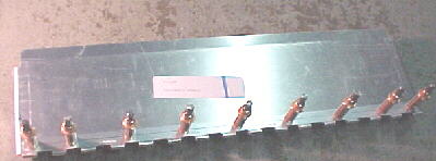
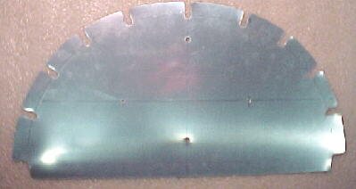
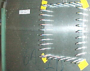
Well, my first building experience on my RV6A has not been a positive one. The drawings call for the 3/4 x 3/4 x .125 angle braces to be 26 3/8 inches long so I cut mine to this length. After doing a very nice job cutting and finishing the angles and radii as specified, I started marking off spacing for the rivets. Something didn't add up here so I got the other premade seat back and measured the angle braces which were nearly 26 11/16! Arrggghh. If you build your parts as per the drawing, your seat back will not be the same as what Van's sends you for the other side. I was not impressed. Other builders- please take note! I hope that the wings don't go like this! With 2500 people before me, I expect the engineering drawings to be correct or if the drawing is correct, then I expect Van's to supply the other piece to be as per the drawing. Also note: the hinges for the base of the seat back are not 15 1/2 inches as indicated on drawing 38, they are 14 1/2.
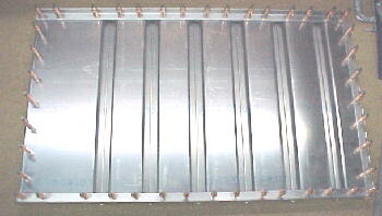
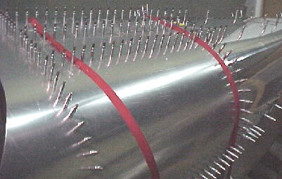
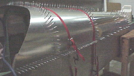
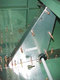
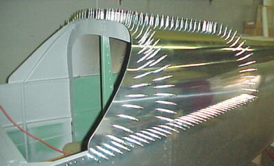
Clecoed seat back
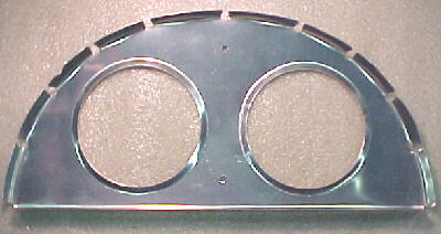
10/03/99 Seat Back
I finished riveting the seat back today. This was my first riveting on the aircraft and it turned out better than the factory made seat back. I Alumiprepped all of the parts and then alodined them. I have decided not to chromate most of rest of the airframe after talking to several AMEs. Their opinion was it would just be extra weight and alodining is very effective and more than adequate in this dry climate.
10/04/99 Van's Service
Today I received my back ordered aileron bellcrank and the 2 items that were shorted from the kit originally. Van's was quick and efficient replacing these items.
10/05/99 Baggage Bay Skins
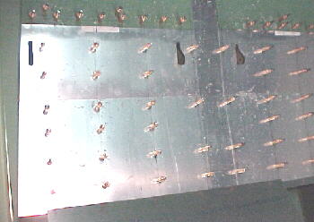
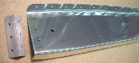
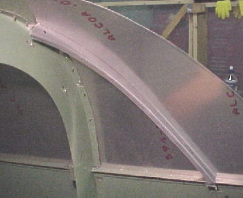
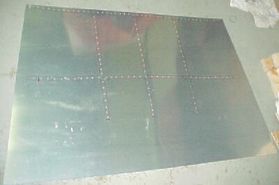
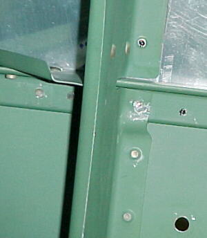
More trials and tribulations. First problem- F-648 had no number on it so it had to be traced through the materials list to be sure that I had the right piece before drilling on it. As can be seen in the photos below, the F-647 R and L skins were massively misaligned from Van's. These are pilot drilled through to the floor ribs by the factory. The skins were mismatched 3/16 to the left of center and a full 3/8 from front to back. As a result, F-648 had to be offset so that the holes did not run off the edge of the sheet. The nutplate hole line is not parallel to the sheet edge which looks bad. Plans indicate that nutplates should be placed in the rear corner junction of F-648 and the bay skins but there is not enough room here. I did not drill any holes here.
I can't say that I am impressed at all with the tolerances of work performed at the factory on these components. Sure, these are just baggage bin floor skins and will be covered up later but I would like to see tolerances of 1mm or less on a metal aircraft.
As I proceeded on to the seat bottom skins I had to pore over 3 different drawings to decipher how the split floor rib was held together. I find the drawing details scattered and not well organized per job. The construction manual is poor in my view as well. There is nowhere near enough detail in the text to be able to quickly locate the parts needed and get to work. I spent only 15 minutes doing actual work out of 2 hours. The rest of the time was spent trying to decide how to align my parts for drilling against the crooked Van's parts and deciphering unclear instructions and scattered drawing details. Van's could save themselves a lot of time, phone calls and money by having all drawings converted to a proper CAD format with proper organization of details, more photos of every assembly and a much more detailed construction manual. This would allow the builder to locate the parts and tools quickly and get right to the task while having a good photo of what the finished part looks like.
10/07/99 Floor Skins
I measured and marked the bulkhead corner cutouts and seat belt anchors and trimmed the F-642s to fit. The sides against the fuselage skins must also be trimmed to fit the slightly rounded countours here. I would not recommend using the procedure in the videos to make the seat belt anchor cutouts first before trimming and fitting the outer edges as this operation moves the F-642 outboard about 3/8 inch which means that the slots for the anchors will no longer be in the right place. This job was quite straightforward but also time consuming. Do lots of measuring and thinking before you cut or drill any holes. One other thing to watch out for here- the 2.5 inch rivet spacing specified on the plans will pretty much guarantee that you hit air with the third row of rivets from the back. There is a cutout in the ribs about here. Also check where your seat mount hinges will be mounted before drilling the seat to rib holes. You may wish to move the rivets or hinges a bit here. The rudder pedals can be moved fore and aft slightly to compensate for leg length but you can tell very little about where the seat hinges should go at this point. Van's suggestions seem as good a place as any to put them. I moved mine aft about 1/2 inch because of my long legs and the fact that I plan to wear a chute.
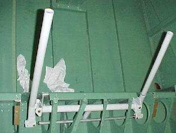
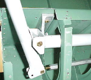
10/13/99 Seat Back Braces and Mount
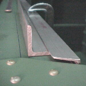
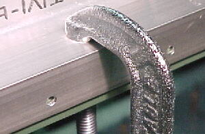
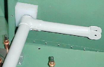
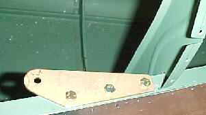
The seat back braces, F-638 were trimmed as per the plans and the aluminum hinges were cut. Cleco side clamps were used to hold the hinges in position while drilling through both components. These were straightforward and fun to build with no surprises.
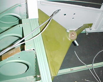
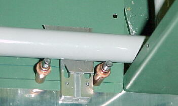
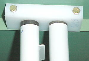
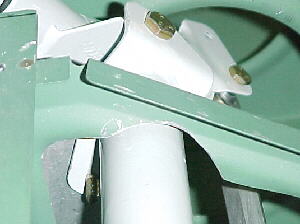
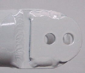
The 3/4 angle seat back brace support which is riveted to the main cabin cross brace, F-605F, was cut and shaped, then clamped in position with a couple of pieces of 1/8 inch angle stock underneath to establish the 1/8 clearance specified. I predrilled the angle with 2 inch spacings on the drill press first, then drilled through the F-605F, clecoing as I went. I did find that the F-605-F distorted slightly and that I ended up with about .115 clearance instead of .125. The F-638s may fit pretty tight as a result. You might want to shim these up slightly. Certainly, the seats won't flop forward unexpectantly while flying solo.
F639 and F-640 forward floor skins were carefully trimmed to fit around the spar housing structure and fuselage sides. Proceed slowly here. I found the 639 skin 1/8 shorter than specified so overlap on the floor rib was slightly reduced. I then reached another stumbling block. The stick cutout holes overlap the floor ribs. Drawing 37 shows a reversed rib flange but nowhere does the manual describe what should be done here. I had to E-mail Van's. I got a reply the next day indicating that the portion of the two ribs needs to be cut off and a piece of 3/4 X .065 angle should be riveted to the floor rib. This is then drilled to accomodate the seat skins.
10/24/99 More Problems
After 1.5 hours of poring over drawings 38 and 47 and the manual for the backrest brace, I cannot figure out where F-685A is placed, which sheet of material to cut it out of (I didn't get any .040 2024 of the correct size with the kit), how many are required, what the bearing block assemby in the drawing is for and where to find it. The drawings really suck here and the manual makes no mention of this assembly nor is there any picture of this in position. Stalled yet again because of inadequate drawing detailing and documentation.
Van's answer was that this assembly is not required with electric flaps fitted. This was a relief but the manual does not state this fact anywhere, nor does the drawing. A simple " not required with electric flaps" note on the drawing would do.
11/15/99
I have been working on the floors for a couple of weeks. There is a lot to do here. Nutplates must be mounted to make the center and front floor skins removable. Hinges are placed to make the seat backs adjustable. Lots of drilling and deburring. They are finally alodined and finished.
I looked at my friend's Glastar yesterday which is about 3/4 done. What great manuals Stoddard Hamilton supplies compared to Van's. He has 2 large binders for his construction manual. The Van's quickbuild has only 40 pages! The Glastar manual has a nice index, everything broken down into sections and individual assemblies, excellent assembly drawings for each part and they list fasteners and drill bit sizes used for each assembly. Very professional. He has not had to contact the factory once for help. I have contacted Van's 6 times in 2 months. I think that building the Glastar would be a calming, enjoyable experience whereas I find the RV6, very, very frustrating at times because of the poor manual and drawings. This reduces motivation to work on it. Before plunking down your money for a kit, order the manuals and talk to other builders first if you can. You may decide on another aircraft. The RVs are popular because they are great airplanes that do most things very well. You just have to get it done to enjoy that aspect.
11/21/99 More on Manuals
I looked at a friend's almost completed RV8A yesterday which was undergoing its final inspection. He showed me the drawings that Van's supplied for his aircraft. They are drawn by a different person and are really nice with lots of assembly detail and 3/4 perspectives, much nicer than the drawings that came with my RV6A. He hasn't had to contact the factory once during construction. Apparently the plans provided with the newer RV8 QBs are even better as there is another under construction in another hanger nearby. At least Van's is working to improve the RV8 drawings. How about the RV6?
I riveted the seat bottom hinges to the floor skins after finding yet another mistake on the plans. They called for -5 rivets. This is incorrect. -4 are the correct length here.
11/25/99 Armrest
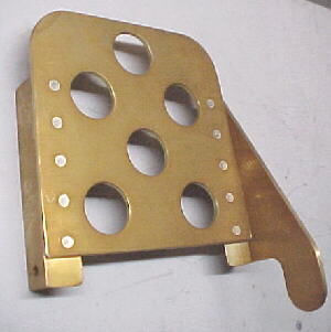
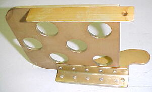
This was the first of many wood projects needed on the RV. Particle board form blocks were cut out according to the preview plans drawing as the required drawing 29 was not included with the kit as it should have been. It should again be noted that these plans did not agree with the part made by Van's already riveted to the right fuselage side. I modified my part to match this piece and not the plans. This was a straightforward but time consuming project. The L bracket and armrest were alodined and are ready to be riveted in place along with the left canopy sill piece.
12/04/99 More things to watch for
If you are riveting in the left canopy sill piece, be aware that the 2 rearmost rivets are #4 and need to be -10 long to be cut to the proper length as they penetrate multiple layers here. Drawing #36 show all rivets here as AN 426 AD3-5 which is incorrect.
02/16/00 F-609
I made the forming blocks and cut out the blank for the F-609 rear fuselage bulkhead. After a bit of work, it was all done with no surprises.
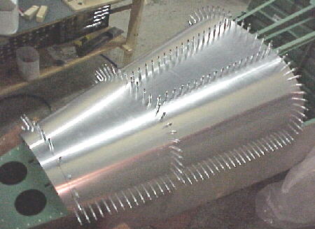
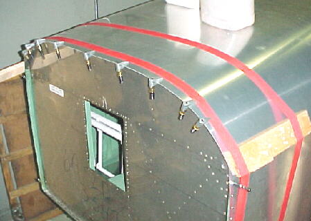
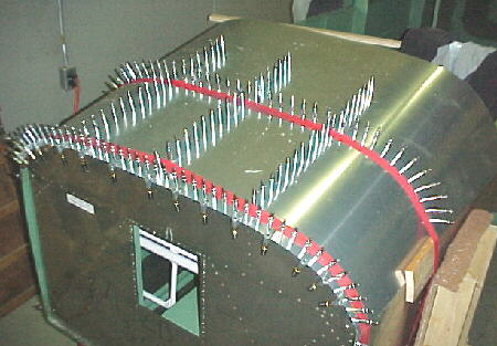
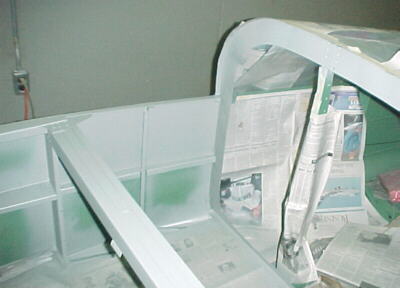
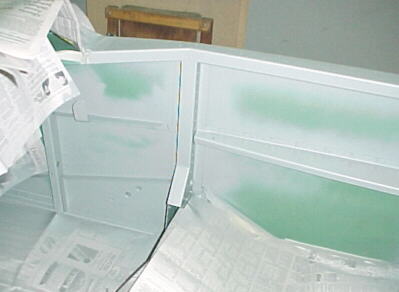
02/23/00 Rear Fuselage Skin
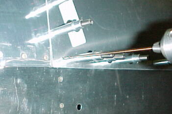
I used 2 cargo straps to hold the skin in position with two 2 X 2 boards along the bottom edges to prevent bowing. This worked much better than just the straps. I marked the inside of the skin around the stringers and formers, removed and marked the rivet spacing. I drilled the skin, then clamped it back on the fuselage and drilled through from the outside, clecoing each hole from the middle top, outwards. Once this was done, I drilled through the main longeron holes from inside and clecoed. The skin and fuselage parts were trimmed, deburred and dimpled. The main longerons were countersunk. Everything has turned out well so far although I was disappointed that Van's didn't drill the rear top longeron rivet holes in the same place on each side of the fuselage meaning the the skin had to be trimmed with a curve in the rear right side to allow for the rivet to go there.
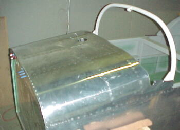
Forward Rear Fuselage Skin 02/26/00
After much searching in the plans and manual for details on fitting this skin, I pretty well gave up here. There are so many wrong references in the manual to drawing details and a lack of useful information as to be essentially useless. There is no reference to skin overlap for instance anywhere and the reference to draw a line 1-2 inches aft of the canopy frame for skin trimming seems absurd. Which is it, 1 or 2 inches? Other details for fitting the center canopy slider and side stiffeners are equally absent or unclear. In the end, I marked at the canopy frame to leave lots and trimmed here. I overlapped the skin 3/4 inches on the aft skin.
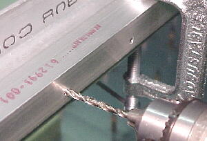
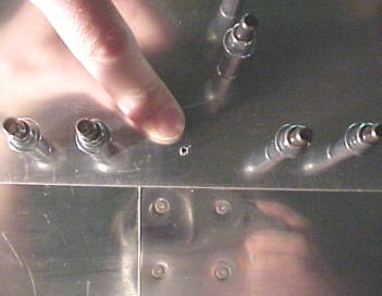
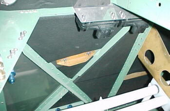
Back drilling longeron rivet holes
03/01/00
After searching the manuals for some tips on installing the F-6111 braces for half an hour, I gave up. I could find no text relating to these. The parts from Van's fit very poorly. I could only assume that they had to be trimmed about an inch to fit the contour of the fuselage skin. I did this and fit them to the skin as close as I could figure in the drawings.
07/03/00 Flap Actuator
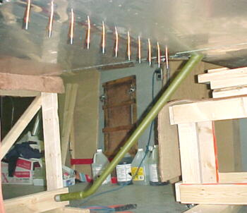
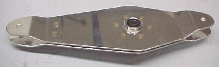
It had been a welcome change building the engine mount which had nothing to do with Van's plans or manual. On returning to airframe work again, I was immediately met with the usual lack of text and drawing detail when getting to the electric flap system. First of all, Van's cleverly put the flap torque tube center bearing block (F 680) in with the rudder parts. It has no part number on it and you have to search the inventory list on your best hunch to locate it. All other flap hardware in in a separate flap hardware bag (926-1). Why would they do something like this? The flap torque tube as well as the rudder bars were masked on the wrong side when powder coated, making orientation confusing.
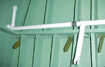
Flap torque tube masking
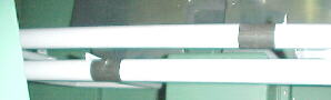
Rudder bar masking
There was no text describing how to locate the torque tube for height above the floor or how to split the center bearing as it is in one piece to start with. Two EF-606s are supplied when only one is required. The photos appear to show angle brackets in place on the front side of the bulkhead where the outer bearing blocks are bolted to, yet there is no reference to these in the plans or text.
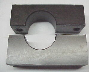
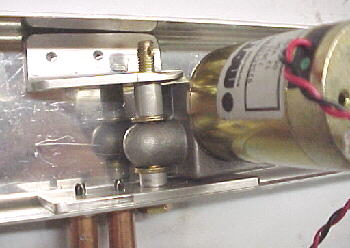
EF680 split with bandsaw. .032 washers will be used to space halves to correct 1 inch ID.
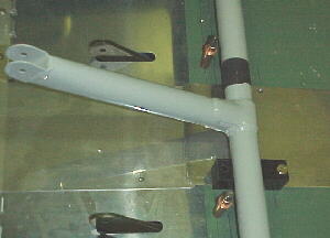
07/06/00
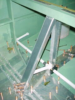
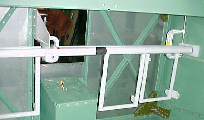
Through a process of elimination, it was decided that the center F-680 bearing block must be mounted with its thicker end towards the floor to permit the correct height of the outer bearing block bolts above the floor skin. Spacers about .450 thick were placed under each outer end of the torque tube to establish an even height with F-680. A 3/16 drill was carefully hand turned through the outer bearing block holes to mark the bolt positions on the bulkhead for drilling. These were center punched and drilled. The plans say to locate the front bottom bracket 10 inches forward on the front baggage bay former. The manual says 9 inches??????
Spacers under tube
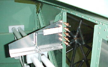
End bearing blocks
07/13/00
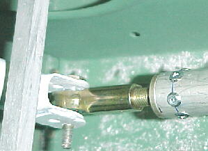
I made the side cover plates and riveted the bottom angle brackets onto the front and rear uprights. I looked at the plans and manual for some indication of torque tube resting position or travel. There are none????? The plans say to locate the upper pivot point about 3 inches from the top of the channel. If you do this, the actuator does not have enough travel to lift the torque tube fully. Since there is no reference to limits, set points or travel, you begin to question whether this is correct. The hole in the actuator end of the tube is factory drilled at -3 yet they call for a -4 bolt. I guess you drill it out. No reference to this again????? Fun, fun, fun... It appears as though the manual for the electric flaps was written originally for completed aircraft originally fitted with manual flaps and was never properly written for aircraft under construction.
07/17/00
More drawing detail errors: Section B-B shows a bushing length of 5/16 inch on the inner actuator end. This is not even close. It needs to be around .445 inches. EF 606 must have its corner heavily radiused to fit inside EF 601 due to the bend radaii. The drawing incorrectly calls for AN 960-10 washers on a -4 bolt. These should be 960-416 washers.
07/20/00
After lots of measuring and trimming, the flap actuator structure and covers are finally done. One more word of caution: The plans call for the angle bracket holding the bottom of EF-602 to the floor to be up against the F-680 center bearing block. If you do this, there is no room for the nutplates for both parts. I moved the angle mounting aft about 1/2 inch which also kept the EF-602 vertical in the fuselage.
07/22/00 Elevator Bellcrank
One of the few straightforward jobs on the RV6. This was actually fun to build with no surprises!
08/06/00 Rudder Bars
So far, the rudder bar construction and installation has gone relatively smoothly. There are some more minor mistakes on the plans for rivet spacing on the rudder bar brace and the usual lack of drawing information. How about a photo of the completed bar/brake assembly in the QB manual?
Note improper factory masking on powder coated rudder bar
Rudder brace

08/08/00
The fabrication of the brake pedals was fairly straightforward.
08/13/00 Sticks
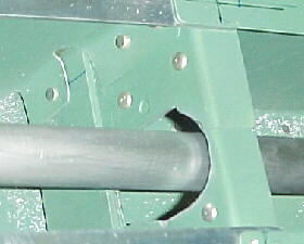
Van's has designed a clever and lightweight control linkage. The floor ribs are not cut or punched to anywhere near the right dimension to clear the control torque tube. The ribs have to be massaged over 1/2 inch in places to establish enough clearance for full movement.
Quite a lot of time was spent machining and reaming the brass stick bushings to proper dimensions and the stick weldments as well which were too wide for the control column capture.
08/17/00 Elevator Pushrods
As stated above, when critical dimensions are not on the drawings, things down the line can experience problems. I went to mount the elevator bellcrank and guess what? Not a single dimension to properly position this critical component. Not only this, but various views of this part depict different positioning from 1/8 to 1/2 inch from the belly skin. I finally got this mounted in what I think was the correct poistion. A very poor job again on Van's part.
I found out that the front elevator pushrod hits the floor skin near full forward stick deflection. It looks like this is a design oversight and I will have to drill the hole lower and add some webbing to correct this. Finally, the plans list the forward pusrod length as 47.5 inches. Don't make the tube this length and rivet the ends on or you will be ordering new parts. Mine worked out to be about 46.5 inches. Test fit the piece in your aircraft before cutting and finishing!
08/21/00
I fabbed and welded on some new pieces to extend the control column rod end mount about 5/16 inch. This fixed the binding problem and also lowered the front pushrod a bit which helped interference through the first bulkhead passage. I had to grind a LOT out of here and the pushrod would have rubbed on the floor had the pushrod not been lowered on my aircraft. This is a design oversight in my opinion.
08/30/00 Shoulder Harness Mounts
This was a straightforward job. The holes were drilled in the longerons, parts alodined and bolted in place. No surprises.
Firewall Cover Plate
After finding out that I had plenty of engine clearance from the firewall, I decided to make a new flate cover plate to replace the original recessed cover. This was fabbed from .016 stainless and dimpled for flush rivets. To make the center section more rigid for noise reduction a cross bace was riveted across the bottom of the hole. This was made from .065 X 1 6061 angle.
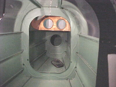
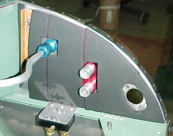
Instrument Panel Mounting 09/11/00
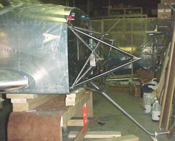
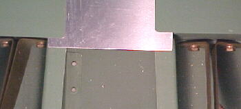
Here is yet another case of frustration with the plans. After carefully fitting the panel to the prescribed dimension in the drawings, I found yet another howling error. The panel did not have the correct angle with the upper front skin.
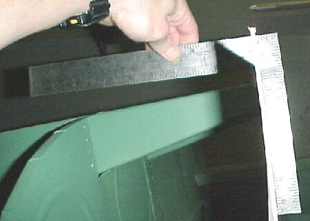
The plans specify that the lower base of the panel should be 23.0 inches from the firewall. As you can plainly see in the photo above, the perpendicular angle to the upper ribs does not match. These must be aligned for the 90 degree angle to attach the top skin. Again, by measuring the 1/4 scale drawing, SC-3, you get a dimension of 22.5 inches and the actual correct dimension is about 23.5 inches on my aircraft. This is only a 1 inch difference! It is really hard to believe that there are so many glaring errors on the plans after over 10 years on the market.
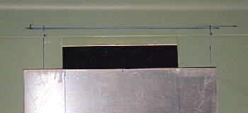
09/27/00
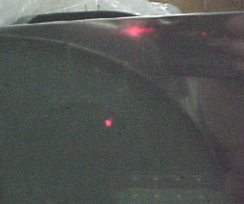
I built a new panel, adding another inch to the lower dimension for more room. I marked the front panel face by extending the top skin line with a straight edge. This is difficult as Van's didn't do the most accurate job of aligning and trimming parts here. I backed up these lines by using a laser pointer to confirm position. I trimmed leaving about .125 inch for final fitting with the skin in place.
10/05/00
I laid out the front, top fuselage skin and marked the stringers and formers from the inside. I prefer this method to drilling from the inside as Van's suggests.


10/11/00
I strapped and clamped the skin in place and drilled through the formers and stringers, clecoing as I drilled.
12/29/00
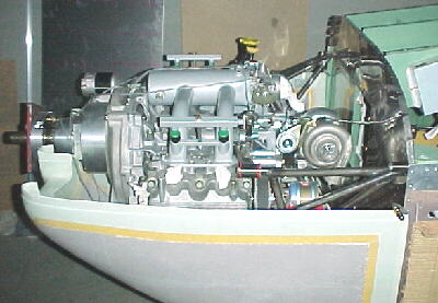
I trimmed out the lower cowl to clear the nose gear support structure to enable trial fitting of the cowl for systems mounting clearance. Suddenly it looks more like a plane than a boat.
05/26/01
The aft upper skin was riveted on using -6 rivets on the longerons.

06/07/01
Van's already installed rivets on the inner skins along the upper longerons. This leaves two gaps in the riveting at formers F606 and F607 which can cause unsightly gaps. I drilled another hole next to the existing rivet, 3/8 inches forward at the F606 former. This bridges the gap nicely.
At the next former, F607, I found it necessary to drill out the existing rivet, fish out the parts from between the skin and longeron and drill through this hole from the inside so that the rivet goes through all the plies.
06/18/01
I got some enamel to match the color of the instrument panel mixed up and put in spray cans. I masked off and painted all the exposed areas which would not be covered by fabric. I wiped down everything to remove dust and marker lines. Once this was done, we clecoed the top skin in place for the final time ans started riveting. Some shims had to be placed between the formers and skin near the longerons to take up some pretty big mis-matches from Van's.
10/01/01
I spent several hours fitting 1/4 closed cell soundproofing to the firewall, cabin sides and floor prior to finally riveting the front, upper skin onto the fuselage. 1/8 inch soundproofing will be glued to the upper skins. This material is available from Aircraft Spruce in various thicknesses, is lightweight and cuts easily with scissors.
10/06/01
Finally riveted the front upper skin on.
04/02/02
After much massaging, filing and struggling, I got the main gear mounts to bolt in. The nose gear leg went right in with no work.