

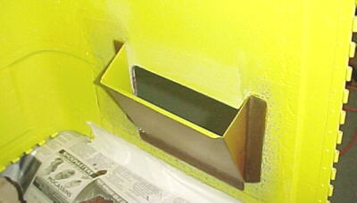
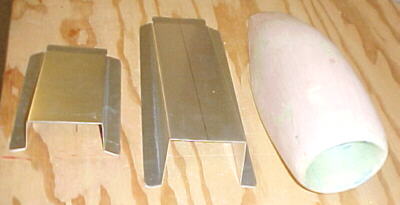
Preparation
One area where I found the Van's manual quite good was the extensive coverage of flight testing and many of the recomendations and warnings were taken into consideration. I put in 75 hours on a Grumman Tiger to get current in a similar type of aircraft and get the 100 hours PIC required to do the test flying myself. The latter hours were flown from the right seat to get used to this perspective as our RV6A is also flown from the right. I thought of getting someone more experienced to do the initial flights but decided against this as the aircraft systems are so much different from standard aircraft. I'd hoped to get a flight or two in a friend's RV6A but our schedules never meshed.
Over 15 hours of ground running and taxi testing were done to work out all the bugs before attempting to fly. Fast taxiing up to 45 knots with full power were eventually done. I obtained a USAF issue Nomex flight suit, gloves and helmet as extra protection. Checklists were refined many times as ground testing showed some flaws. The aircraft C of G was calculated to be in the center of the envelope. I flew the Tiger, the morning of the first test flight to be totally current. We waited for a day with a steady wind right down the runway. I had test cards prepared for the exercises that were to be performed.
Unfortunately I had to wait for a half hour on the ground for the very busy traffic to clear a bit. The controller sent me out further than I would have liked from the airfield before I could turn back and I had to drag it in for the first landing behind a 172 at 75 knots but things turned out fine. I stayed within 3 miles of the runways at 6500 feet at all times. Field elevation is 4000 feet. I was so busy that I didn't get the test card filled out quite in order. My advice is to prepare well, be current and don't be in a rush.
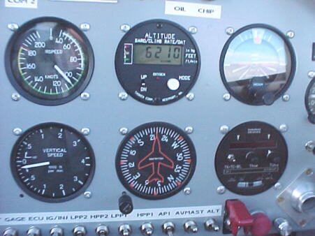
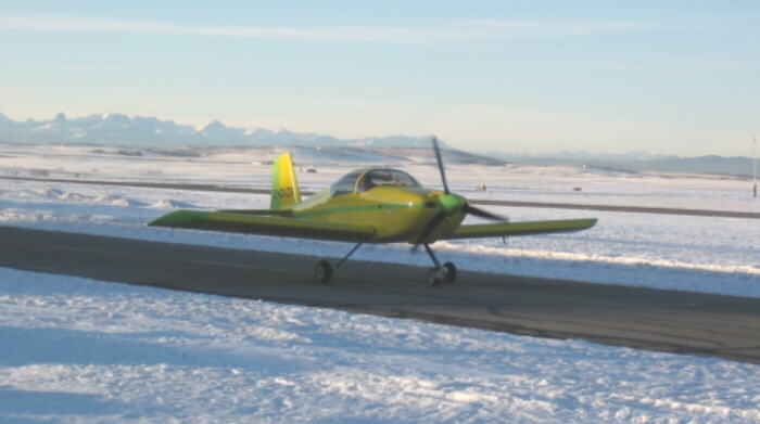
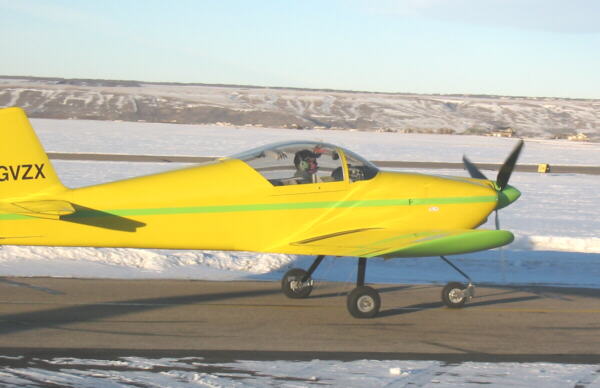
First flight took place on Nov. 30/03 and lasted 27 minutes. Maximum altitude obtained was 6700 feet. Max airspeed 105 knots. Minimum speed 65 knots. Ambient temperature 0C. Aircraft flew hands off with good trim and stability. Power setting for takeoff was 4750 rpm and 40 inches MAP. Ground roll was about 500 feet. No flaps were used during the flight. Controls were light, responsive and well harmonized. EGTs ranged from 885F at idle to 1174-1277F in flight at various power settings. The GPS was used to verify ASI readings by doing upwind and downwind runs. This is recommended if no chase plane is available.
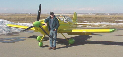
It is an amazing feeling to fly something that you built yourself after seeing it as a pile of aluminum only a few years ago. A profound feeling of relief and accomplishment plus a good dose of trepidation when the throttle was advanced and you know this is it!
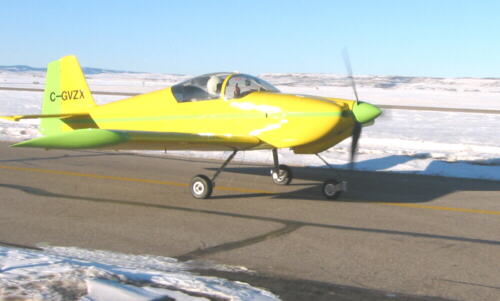
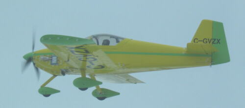
The RV grin. The relief is hidden under the visor! Sony DV cam records engine parameters.
12/05/03
VZX's primary function is to prove the turbo Subaru concept and provide in house testing of our engine management systems for aircraft use. We'll also be trying to correlate and quantify engine cooling data, intercooler and turbocharger data as it relates to aircraft performance. We'll make this information freely available on our website for everyone. There are no plans to offer engine packages.
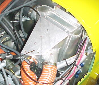
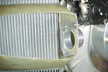
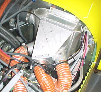
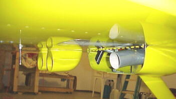
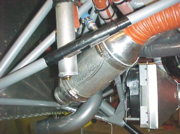
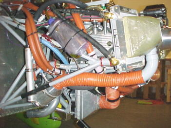
The RV has been checked out again and some slight mods have been made to try to improve cooling and temperature studies. The aircraft is equipped with an SDS digital engine monitor recording multiple temperatures and pressures with a scanning feature and Sony camcorder for recording. We've added two more coolant temp sensors for a total of four. We measure coolant temp at the thermostat, in the coolant discharge manifold and in the return header tank. The cowl flap has been removed to try to increase exit area. The small fan on the left rad has been removed as it blocked about 20% of that rad's exit area. A line restrictor in the turbocharger water hose was removed. Testing will concentrate mainly on engine development for the time being. Stay tuned.
12/08/03
Flight testing proceeded with 3 flights on the Dec. 6/7 weekend. Airspeeds were slowly worked up at various power setting and hundreds of temperature and pressure measurements were taken. The aircraft was not fitted with leg farings or wheel pants. Half flaps were lowered at 75 knots. There was a noticeable nose down pitch change. Stability was neutral in pitch or slightly negative. In roll it is slightly positive. Yaw is positive. The aircraft demands to be flown at all times but is delightful to fly with crisp response in all 3 axes. The IVO prop was cycled from fine to coarse with further testing to be done there. I find no problem slowing down and landing flapless. Landing and takeoff rolls are short. The RV6 has an excellent combination of speed, handling and docility. The only major snag so far is no mode A or C on the transponder.
King GPS is wonderful
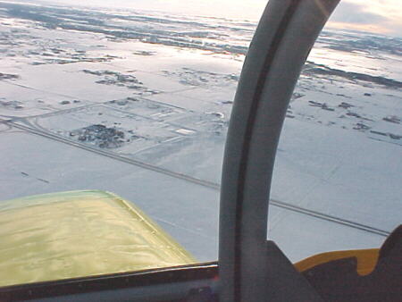
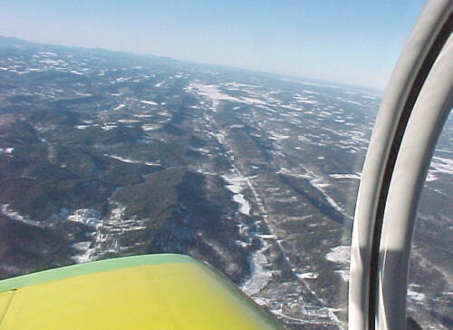
Turning over Springbank airport
Initial Airspeed Checks
3750 rpm/ 22 inches MAP IAS 105 knots TAS 114 knots
3750 rpm/ 25 inches MAP IAS 112 knots TAS 122 knots
4000 rpm/ 24 inches MAP IAS 115 knots TAS 125 knots
4250 rpm/ 30 inches MAP IAS 125 knots TAS 135 knots
5000 rpm/ 35 inches MAP IAS 147 knots TAS 160 knots
So far, it looks like our Subaru turbo powered RV6A is in the ball park for speeds compared with Lycoming O-360 RVs. We expect to pick up 10-13 knots at 8000 feet density altitude with the fairings and wheel pants on. Obviously at higher altitudes and using the power available with the turbo, we expect our projected max cruise speeds to be in the 190 knot TAS range.
Fuel Flow
3750 rpm/ 24 inches MAP, mixture knob 0%, AFR 12.3 to 1, EGT 1243F, FF 47lbs./hr.
3750 rpm/ 24 inches MAP, mixture knob -5%, AFR 13 to 1, EGT 1282F, FF 45lbs./hr.
3750 rpm/ 24 inches MAP, mixture knob -10%, AFR 13.6 to 1, EGT 1323F, FF 42lbs./hr.
The engine is producing around 80 hp at this setting theoretically. I leaned to a max of -14% showing about 14.2 to 1 AFR and 40 lbs./hr.
Theoretical HP vs. Manifold Pressure and RPM
| RPM | PROP RPM | MAP 30 | MAP 35 | MAP 40 | MAP 45 |
| 4000 | 1818 | 107 | 125 | 143 | 161 |
| 4250 | 1932 | 114 | 133 | 152 | 171 |
| 4500 | 2045 | 121 | 141 | 161 | 181 |
| 4750 | 2159 | 127 | 148 | 170 | 191 |
| 5000 | 2273 | 134 | 156 | 179 | 201 |
| 5250 | 2386 | 141 | 164 | 188 | 211 |
| 5500 | 2500 | 147 | 172 | 197 | 221 |
Other Observations
The SDS EM-4 4F engine management system has worked flawlessly so far. Just advance the throttle and fly it. No carb heat, no mag checks no mixture to worry about.
The engine is quite smooth in the 3750 to 5000 rpm ranges. There are certain mild vibration periods at 3500 and below, depending on prop pitch settings but since these are not in the cruise areas, they are not a big concern at this time.
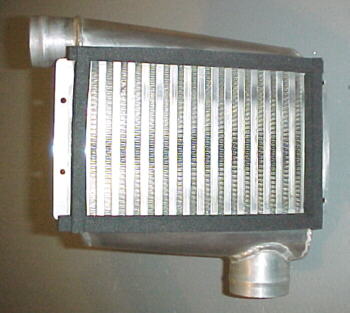
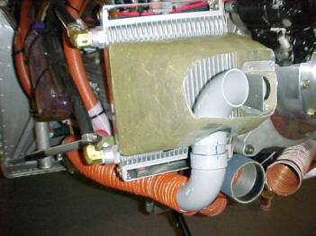
So far, I'm not happy with the intercooler effectiveness. Changes to ducting will probably be required.
The heating system is very effective with no "hot metal/ oil" smells characteristic of heat muff type systems.
Noise levels are similar to other GA aircraft. Good headphones are mandatory. I'm glad I put substantial sound proofing and upholstery in. I can only guess that bare RVs are very noisy inside.
I find the nose high attitude and not so good forward visibilty a little different from something like the Tiger but you get used to it.
12/09/03
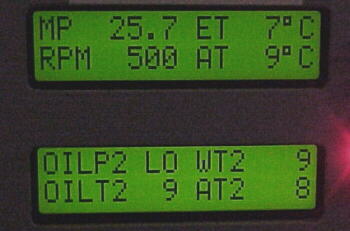
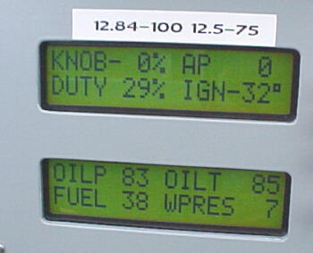
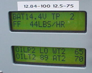
Temperatures and Pressures
The chart below has some of the logged engine parameters so far recorded:
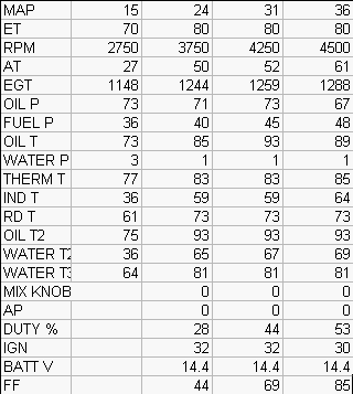
Abbreviation key:
MAP- Manifold absolute pressure inches hg
ET- Engine coolant temp in C
RPM- Engine rpm
AT- Engine air temp after intercooler in C
EGT- Exhaust gas temperature in F
OP- Oil pressure in psi
FP- Fuel pressure in PSI
Oil T- Oil temp in filter housing in C
WP- Water pressure in psi
Therm T- Coolant temp at thermostat in C
IND T- Compressor discharge temp in C
RD T- Reduction drive oil temp in C
OIL T2- Engine oil temp in main gallery in C
Water T2- Engine coolant temp exiting radiators in C
Water T3- Engine coolant temp exiting engine in C
Mix knob- SDS mixture knob position in %
AP- SDS acceleration pump value
DUTY- Injector duty cycle in %
IGN- Engine ignition timing in degrees BTDC
Batt V- Battery voltage
FF- Fuel flow in lbs./ hr.
12/10/03
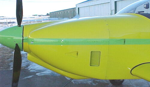
The next flights will involve cooling, radiator and pressure testing to determine the best course of actions to improve cooling and reduce drag if possible. Some pressure studies with the cowl flap, revised exits and reshaped inlets are planned.
12/12/03
We did a 1.1 hour test flight on Dec. 11. We tested a modified GPS mount to stop the unit from vibrating in the panel, this was successful. The transponder problem was fixed with a reconnection of the antenna lead with a better retaining method. The IVO propeller brushes were checked and found to be worn unevenly. It looks like these will need to be changed about every 25 hours of operation. We found that the reduction drive chip detector magnets had lost their flux strength due to heat possibly so we need to change these. We instrumented the oil sump with a temperature sensor to see how effective the oil cooler was. It reached a maximum of 110C while after the cooler saw 85C. The 20-25C drop is good but we hope to improve that with revised ducting. Fuel was run down to 1/4 tank in flight to test for proper feed. We see a 50-75F higher EGT reading in cylinder #2 and may try swapping injectors to see if we can determine what is causing this-air flow or fuel flow differences. In flight, I saw a rate of climb of 1500 fpm at 35 inches and 4750 rpm in full fine pitch at 90 knots. Weight was around 1400 lbs., field elevation 4000 feet, ambient temp -7C. Obviously there is a lot left if we can keep the engine cool and run 40 inches and 5000 rpm for the climb. Approach is at 75 knots, over the fence at 70, touchdown at 60.
Ran another fuel flow/ speed test as well. 4500 rpm/ 30 inches gave 142 knots TAS, burning 63 lbs. per hour. Mixture was leaned 5%.
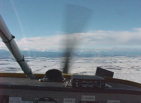
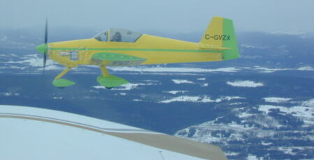
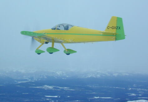
Just down from the 12/11/03 test flight. Rocky mountains in the background. A nice winter day for flying.
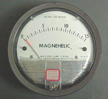
We'll be instrumenting the cowling inlet and outlets with these sensitive pressure gauges to test pressure differentials across the radiators with different exit areas.
12/14/03
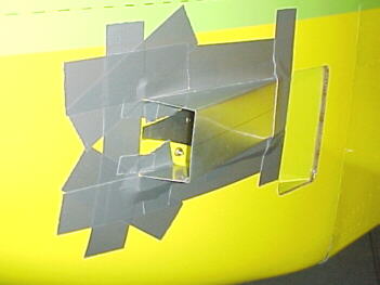
I started thinking that the cooling problems might be caused by a lack of exit area in the cowling. Inlet area on my RV is about 49 square inches, exit area is about 50, so roughly the same. The rule of thumb says we should have 1.5 to 2 times the exit area so we're not even close. We did 2 short flights to check cooling, propeller operation and handling with half and full flaps.

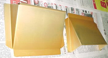
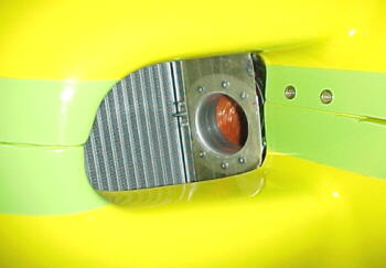
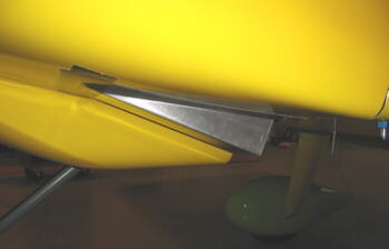
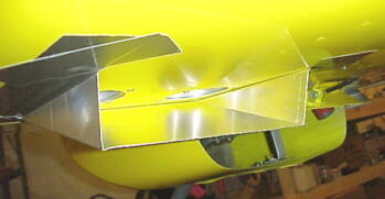
Right gauge reads pressure in left rad inlet, left gauge reads pressure in cowling
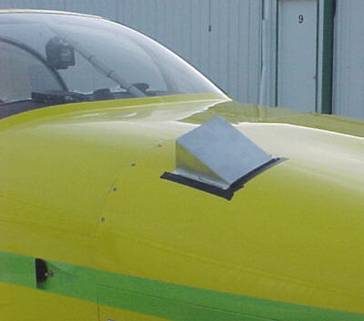
I fabbed up a quick exit scoop to take the place of the oil filler door. This is located in a low pressure zone. Exit area was 13 square inches. We did baseline pressure readings without the new exit scoop, then came down and fitted the scoop and took new readings. As you can see below, there was a reasonable change in pressure and we saw substantial drops in all the heat exchanger temperatures.
Tests were done at -7C and 6500 MSL.
Without scoop
| IAS Knots | Inlet Pressure | Outlet Pressure |
| 100 | 5.5 | 3.0 |
| 115 | 7.0 | 4.0 |
| 125 | 8.5 | 4.5 |
With scoop
| IAS Knots | Inlet Pressure | Outlet Pressure |
| 100 | 5.5 | 2.6 |
| 115 | 7.0 | 3.5 |
| 125 | 8.3 | 4.0 |
Running at the same power setting of 4000 rpm and 26 inches, we saw the water temperature drop 10-20C, air temp 19C, oil temperature in pan 5C, induction temp 15C, Oil temp after cooler 15C so it looks like we might be on track.
The IVO brushes were finally getting short at 26 hours so they were replaced. Note only one brush seems to wear.
The mountains through the windshield, note exit scoop at right
I ran some tests with the prop at a fixed throttle setting 24 inches MAP. The results were interesting. Pitch angle is judged with a 0-10 amp ammeter. In transit through neutral runs about 2 amps, peak at the 2 stops is about 6 amps.
Full fine gave 4500 rpm and 115 knots IAS
Neutral pitch gave 4250 and 110 knots IAS
Full coarse gave 3750 and 105 knots IAS
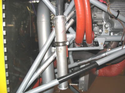
The oil and water temps on the Subaru engine are closely related as it is all one big chunk of aluminum and there is substantial conduction. Since the redrive is also aluminum and bolted to the block, it too receives a lot of heat transfer from the engine.
Contemplating the high coolant temps during the climb, I decided to modify the left rad inlet to reduce turbulence. I fabbed a sheet aluminum fairing and taped it into the lower rad duct. On the next flight, I was finally able to climb at 30-35 inches without the coolant temp exceeding 90C for the first time. This was starting to get encouraging when in level flight, the coolant temp soared to 110C suddenly. I pulled power back to idle and landed. The engine had puked out a lot of coolant. After reviewing the video, it looks like the thermostat must have stayed shut for some reason as ET went up on two sensors while coolant from the rad outlet continued to get colder at the same time. The thermostat will be coming out after this so see what effect it has.
The chart below tracks the progress of various temps on this flight. Note the increase in engine temp, water temp 3 vs. the falling water temp 2 which is the rad exit temp.
| MAP | 24 | 26 | 26 | 26 | 26 | 10 | 6 | 15 | 10 |
| RPM | 3750 | 3750 | 3750 | 4000 | 4000 | 3000 | 2500 | 3000 | 1500 |
| ET | 70 | 70 | 80 | 90 | 110 | 110 | 110 | 80 | 80 |
| Oil T | 85 | 85 | 85 | 85 | 89 | 89 | 89 | 83 | 81 |
| WT2 | 53 | 59 | 43 | 45 | 45 | 45 | 42 | 30 | 38 |
| WT3 | 65 | 65 | 85 | 93 | 93 | 93 | 85 | 81 | 81 |
Note WT2 generally stays around 55 to 65C in level flight and ET and WT3 should be stable at 70-80C. The oil temp also started to rise when the water temp went up. As the engine lost a fair amount of coolant when it went to 110C, the ET never went back below 80C on the descent or landing.
I dropped half flaps at 80 knots to check handling and power required to maintain altitude. The flaps cause a lot of drag. Dropping full flaps at 75 knots caused a lot more drag and the aircraft felt like it was wallowing. I did a landing with half flap which did improve over the nose visibilty but prefer the handling and flare charateristics of the aircraft in clean configuration. I feel the flaps are totally unecessary for most people operating from 2000 ft.+ paved runways.
12/19/03
We did a short flight without the thermostat installed on Dec. 18/03. Temperatures stayed down quite well but water pressure still spiked to 22 psi during the climb. It appears as though the water is moving too fast without the thermostat in place as we saw only a 3-10C difference between ET and water exiting the rads. We plan to install a new OE thermostat with a few .125 holes drilled in it as a safety to ensure some water flow at all times. We'll also be trying a bit more air space in the header tank and adding 2 exit ramps on the cowling sides to improve airflow through the coolers.
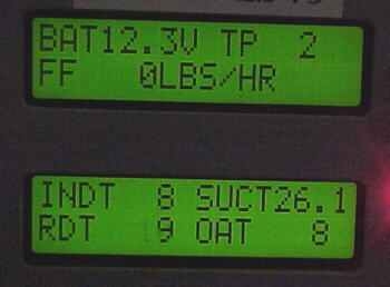
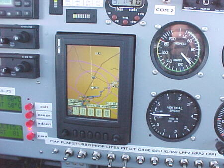
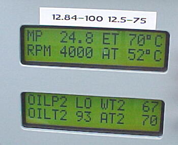
SDS digital engine monitor with 2 of 5 screens shown
12/26/03
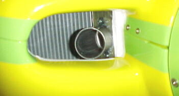
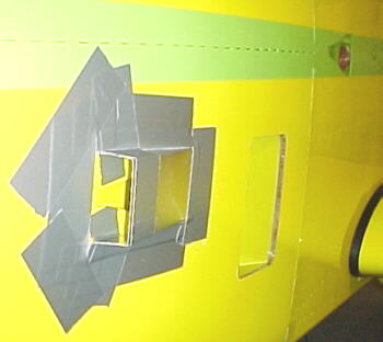
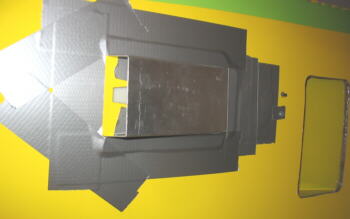
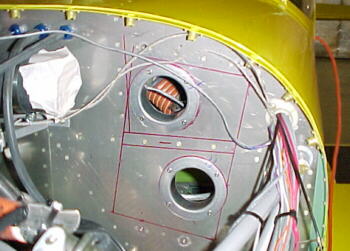
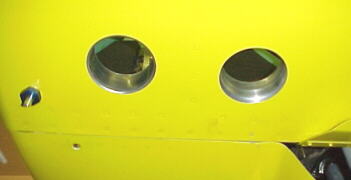
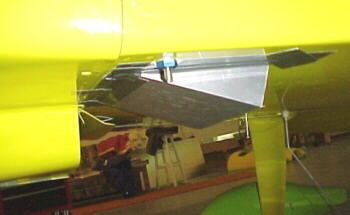
We built some exit ramps from .032, 3003 aluminum and glassed them into the cowling after cutting a hole in each side measuring 4.25 by 6.625. The exit ramps measure 6.625 by 2.125 which add about 28 square inches of total exit area. They are located in a known low pressure region.
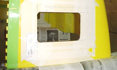
Exit ramps glassed into cowling. Thermostat modified with three .125 holes drilled into base.
I was not too keen on how Subaru designed the thermostat system and felt at times it would be slow to respond and tended to lock up the system by preventing coolant flow and trapping air so I drilled 3, .125 inch holes in the base of the thermostat to have a constant flow of water bathing the bulb and let air pass by. This appeared to work well. The engine was much easier to fill with coolant and now the water pressure and temps act as they should. I also no longer fill the coolant header tank all the way. An air space is left above the return line to allow air and steam to stay above the coolant level without being mixed or entrained and going back into the water pump.
These 3 changes altered the whole personality of the engine cooling. Climbing at 33 inches and 4500 rpm from 4000 to 6500 feet never saw the coolant temp exceed 80C at 80 knots. Internal cowling pressures also dropped. Rate of climb was between 1500 and 1900 fpm. This was a clear indication that there was insufficient exit area on the original cowling to cool this engine properly plus having the exit on the bottom of the fuselage is probably not the best place in the climb due to higher pressures present there. The chart below documents the pressures and temps from takeoff to landing. Some data is missing if the display had glare on the video from sunlight reflection.
| Parameter | Takeoff | Climb 1 | Climb 2 | End Climb | 3 min. Level | Power Run | Descent | T&G |
| MAP | 39 | 34 | 34 | 34 | 27 | 31 | 10 | 35 |
| ET | 61 | 70 | 80 | 80 | 70 | 70 | 58 | 61 |
| RPM | 4500 | 4500 | 4500 | 4500 | 4500 | 4500 | 3000 | 4500 |
| AT | 36 | 46 | 52 | 61 | 47 | 53 | 33 | 47 |
| OIL T2 | 69 | 75 | 81 | 96 | 89 | 93 | 70 | 79 |
| WT2 | 49 | 51 | 53 | 69 | 51 | 61 | 41 | 48 |
| WT3 | 67 | 67 | 73 | 73 | 63 | 69 | 53 | 59 |
| Oil P | 93 | 83 | - | - | - | - | - | - |
| Fuel P | 48 | 44 | - | - | - | - | - | - |
| Oil T | 70 | 75 | - | 93 | 91 | 89 | - | 73 |
| WP | 13 | 13 | 9 | - | 13 | 11 | 3 | 11 |
| EGT | 1212 | - | 1326 | - | 1240 | 1301 | 1075 | 1330 |
| INDT | - | 46 | 55 | 70 | 55 | 64 | 35 | 41 |
| RDT | - | 27 | 30 | 47 | 50 | 63 | 59 | 53 |
| Therm T | - | 69 | 75 | 93 | 81 | 83 | 67 | 79 |
We also tested the cowling pressures after the exit ramps were installed by removing the top exit over the oil access door and re-installing the door. This was found to make no difference in cowling pressures nor in temperatures. A climb at 35 inches and 4500 rpm showed all temperatures in the green. With the exit ramps, we sit at about a 1 to 1.5 ratio, inlet to outlet area. A test was also done on the intercooler plenum pressure. This showed less pressure on the inlet than the cowling internal pressure, indicating a negative flow through the core. We'll try to confirm this with wool tufts in flight with a photo plane later. This would explain the poor intercooler performance.
12/28/03
Two flights on this day were mainly to determine a suitable pressure source for the intercooler inlet. First the pressure probe was placed just behind the spinner back plate. This was essentially the same pressure as the rest of the cowling interior. On the second flight, the probe was moved to the oil cooler inlet duct. This showed the same 7 inch pressure as the left rad duct. The right duct may have space to fit a 2 inch spigot underneath to feed the intercooler. Other tests showed closing the cowl flap caused pressure to increase about 1 inch H2O inside the cowling. The flap may be able to be closed in cruise flight with the exit ramps in place now to reduce drag slightly. We will perform this test at a later date.
When the video was reviewed we saw the following climb performance at 4000 feet MSL, -9C, power setting was 4500 rpm and 35 inches, prop, full fine, weight 1430 lbs. The deck angle is impressive.
| IAS KTS. | Climb Rate FPM |
| 80 | 1800 |
| 85 | 1700 |
| 90 | 1500 |
The takeoff acceleration was also timed at 8 seconds from 0-60 knots with the throttle being advanced slowly on the roll to 4750 rpm and 38 inches.
Some more speeds and fuel flows:
4500 rpm/ 25 inches, mixture -5%, prop neutral, EGT 1336F, 54 lbs./hr., 120 knots IAS at 6500 feet MSL, 128 knots TAS
4250 rpm/ 25 inches, mixture -5%, prop coarse, EGT 1320F, 54 lbs./hr., 120 knots IAS at 6500 feet MSL, 128 knots TAS
4500 rpm/ 30 inches, mixture -5%, prop full coarse, EGT 1355F, 66 lbs./hr., 130 knots IAS at 6500 feet MSL, 140 knots TAS
So far the IVO prop has given no problems. None of the horror stories like loosening or cracking blades.
After doing about 20 landings now, I can say that the RV6A is the easiest aircraft to land smoothly that I have flown. It is a real pleasure to fly.
01/01/04
The intercooler air supply source was moved from the side NACA duct to the right oil cooler inlet duct. Pressure measurements showed that the intercooler plenum pressure was equal to the internal cowling pressure so there was still no net flow through the core. More air mass flow may be required so plans are to install a second 2 inch feed hose to the plenum. Plans are also to install the main gear leg and wheel fairings for the next flights in 2004.
01/05/04
Mods were done to increase airflow to the intercooler. Two 2 inch hoses are now run to the core. We hope to test the pressures soon. The main gear leg and wheel fairings are also installed for the next test flight.
Second intercooler feed hose added to left inlet duct, modified intercooler plenum
01/09/04
We added two ram ducts to the intercooler inlets to measure effect on the intercooler plenum pressure.
The flight tests showed a one inch of water differential with these scoops installed and intercooler effectiveness was substatially increased. Before the second hose was added we saw only a 9-10C drop across the core. With the second hose added this increased only to 12-13C drop and 0.5 inches of water differential. With the scoops and twin hoses, temps were reduced 21-25C. Max AT reached 52C in the climb and ran at 35C in cruise at 25 inches. Ambient was around 0C. The engine was making more power at the same power settings as I could no longer hold it on the brakes during the runup even though ambient temps were warmer than previous test flights. Adding the ram ducts doubled the pressure recovery over the flush ducts so we'll be fabricating a boundary layer side cowling scoop to replace the NACA duct and adding another 2 inch hose to feed the intercooler plenum. We hope that this will increase intercooler effectiveness even further. We'll be making other minor changes to hose couplings, inlet lip geometry and the crankcase breathing system before the next flights.
The aircraft was light on fuel at about 1370 lbs. Rate of climb was as high as 2300 feet/min. at 35 inches and 4750 rpm. The wheel pants on the mains might have been helping as well. The aircraft was noticeably harder to slow down in the descent and the pattern. Some of the air coming into the cabin was reduced due to the intersection fairings being installed also. IVO prop bolts were checked for torque for about the tenth time in 35 hours and took no torque.
Looks like we have picked up 8-10 knots at low power settings with the farings on. Showed 133 kts. TAS at 4250 rpm and 25 inches MAP. The nose wheel fairings should add another few knots.
More photos of the SDS gauge package in flight:
01/19/04
Four test flights on this date were conducted to run more intercooler evaluations. An ME 109 style boundary layer scoop was laid up over a foam core. This supplied two, 2 inch scat hose connections with air. A third hose was attached to the intercooler inlet plenum going to a revised ram duct connected to the right oil cooler duct.
Flight testing showed this worked marginally better than than the last flights with 2 hoses and ram ducts. A maximum drop of 33C was seen with this setup. Pressure differential across the core was 1.5 inches of water at 110 kts. which was about 0.5 better than with only 2 hoses. The next test involved re-installing the top oil door exit scoop to see if the pressure differential across the core and cooling was increased. This showed no gains on either.
The third flight plugged off one hose. Interestingly, this was essentially the same as with 3 hoses feeding the plenum. This would seem to indicate that the area of 2 hoses equals the area of the core air passages and that further hose area gains nothing in net airflow.
The fourth flight involved re-installing 3 hoses but replacing the ME 109 scoop with a simple metal ram duct. This again produced similar pressure and temperature differentials.
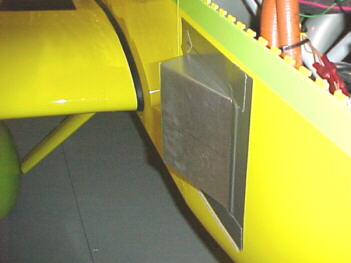
We have now tried several combinations of scoops and hoses. The cowling side scoops are shown below
I'm still not happy with the intercooler effectiveness. Initially it was around 15-20% with one hose fed by a flush NACA duct. This increased to 35-40% with 2 hoses and ram feeds. 3 hoses with ram feeds took this to 35-43%, still quite poor. It seems to increase airflow, we need to increase the pressure differential across the core. Since we can't increase the inlet pressure, we need to decrease the exit pressure. This will involve moving the core forward to allow more space to construct an exit plenum and routing hoses to a low pressure area. Not sure when this will be done as it would seem to be quite difficult.
01/23/04
Our sensitive pressure gauges were set up to read vacuum and we instrumented the left side of the cowling and a rear facing exit scoop. Vacuum on the cowling side was 0.5 inches H2O at 110 kts. On the rear facing scoop it was -1.0 at 110 kts. and 2 inches at 120 kts. This would seem to be highly effective for placing our new intercooler outlets in. This should take our pressure differential from about 1.5 inches to around 6 inches hopefully. The pressure in the cabin was essentially atmospheric. The day was +4C. We saw intercooler effectiveness of 31% in the climb and 40% in cruise. Temp drops were 21-22C across the core with 2 hoses feeding the core. Also fitted was a revised crankcase ventilation system to eliminate the oil mist inside the cowling from the K&N breathers. This worked well and also eliminated the odor coming in though the cabin NACA ducts. Thanks to my good friend Jim Dyck for TIG welding this and other parts up on the plane. Also tested was air temp on the outside of the cowling behind the intercooler inlet scoop. This showed teperatures 20-25C over ambient, indicating that some rad air is spilling out the inlets and flowing down the side of the fuselage. Unfortunately the day was very bumpy with moderate to severe mechanical turbulence so this was a short flight.

Note manometer probe inside duct
Pressure and temperature probes just behind intercooler inlet duct
New oil separator
The next step will be to put two 2.5 exit holes through the firewall and seal the intercooler to the firewall. We'll just dump the air straight into the cabin initially and measure the temperature drop. If this is substantial, we'll route two SCAT hoses to a rear facing belly exit scoop.
01/27/04
The mods are done, ready for the temperatures to moderate for test flying. -34C today! Cutting holes in the stainless steel firewall was a real chore and routing the connecting scat hoses through the maze while lying on your back under the panel was #$#@&!!!** frustrating. Added new extractor scoops over the exit ramps to try to lower internal cowling pressures as well. Scoops are racer taped on for evaluation. If they prove out, I'll fabricate some properly shaped glass ones.
2.5 inch holes cut in firewall and belly for air exits from intercooler plenum
Intercooler exit sealed with foam weatherstripping tape to firewall, new side extraction scoops
Intercooler bottom exit extractor scoop detail
The magnetic chip detector was checked and showed no particles so redrive looks to be in good shape. The 1500F ceramic coating on the header collector is starting to flake off now. Only good to 1300F apparently!
02/01/04
3 test flights were conducted to determine the effectiveness of the revised cowling and intercooler air exits. Testing showed that the best configuration for the intercooler was three, 2 inch SCAT hoses feeding the inlet plenum with the new external exits. This showed a maximum of 51% effectiveness. We hope to boost this slightly with proper streamlined exits guides. The pressure differential across the core was increased to 2.1 to 3 inches H2O at 110 and 125 knots respectively, besting the original setup dumping the intercooler exit air into the cowling.
The revised cowling extraction scoops over the exit ramps showed a increased pressure differential of 3.8 and 4.5 inches at 110 and 125 knots respectively. Ambient was about -15C at the surface and -10C at 6500 feet but I was able to climb at 38 inches and 80 knots with the coolant temp staying at 70-80C for the first time. In cruise flight at 22-25 inches and 4000-4250 rpm, coolant temp sat at 61C with the heater full on. This indicated that the thermostat was completely closed. Water flow through the three, 1/8 inch holes was enough to keep things stabilized. I was seeing a 15-20C drop across the rads. We'll wait for some warmer temperatures to decide whether the external extraction scoops are worth the drag penalty if any and if they aid cooling significantly over the flush exits. With no intercooler air pressurizing the cowling now, the results may not be entirely valid without further testing.
Next, on to propeller testing and speed testing at higher altitudes and some longer flight durations outside the control zone. I see the present prop as being too small as 30 inches MAP gives 4750 engine rpm in full coarse pitch at 6500 feet. There are some indications that 105 inches of pitch with the present prop may be too much as well. We'll try fitting flatter pitched IVO paddle blades with a wider chord after getting baseline numbers with the present one. This paddle prop has a 90 inch maximum coarse setting which is more in line with the 83-86 inch fixed pitch metal props usually fitted to RVs.
02/06/04
After talking with IVO, it would seem that we might not have been getting maximum pitch out of the prop. Even though they have a 10 amp slow blow breaker on the circuit IVO says that max pitch is at close to 18 amps. After taking the prop in the hangar to 10 amps, (we were using 6) the motor sounds very strained and a friend had broken a part in his hub at above 15 amps. I think we'll limit things to about 10-12 amps. In flight using 10 amps, engine rpm was reduced about 250 but with the improved intercooler setup, I was still getting 5000 rpm at only 30 inches MAP. Unfortunately at the rpm we are turning the prop, the 90 inch maximum paddle blade setup would appear theoretically to be not enough pitch for above about 170 knots. This is what IVO also told me. We'll try the new prop at some point and compare.
I did some tests with the heater on and off to watch coolant temperature. With the heater full on, ET was 61C , WT2 was 45C in cruise at 25 inches. With it off, ET went to 90C, WT2 to 46C and it sat there, indicating that the thermostat was open. The thermostat begins to open at 78C. Of course with the 3 bleed holes in it with the heater on, the thermostat is closed fully.
I also closed the cowl flap and saw the cowling pressures at 115 knots go from 6.0 inches inlet and 2.3 outlet to 7.0 and 3.5 respectively. It was interesting to note that the inlet also increased with the flap closed.
I did some more ground speed tests which confirmed the accuracy of the ASI within 1.5% at cruise speeds.
At a power setting of 4000 rpm and 24 inches, intercooler effectiveness was calculated at 52%.
It looks like we picked up 12-15 knots in the higher speed ranges with the wheel pants and leg fairings. Pretty substantial.
A few preliminary speeds:
3500 rpm/ 22 inches 119 knots TAS 36 lbs./hr. at -8% knob OAT -4C 6500 feet
4250 rpm/ 25 inches 140 knots TAS 55 lbs./hr. at -5% knob OAT -4C 6500 feet
5000 rpm/ 30 inches 156 knots TAS 78 lbs./hr. at 0% knob OAT -4C 6500 feet
Next plan is to do some air to air video and photos. We plan to tuft some areas of the aircraft to check airflow patterns as well.
02/08/04
I conducted the climb test required by Transport Canada on Feb. 7/04. The aircraft was filled with fuel and 212 lbs. of sand bags were loaded on board, bringing VZX up to 1750 lbs. The weight and balance calculation showed the C of G at about 2.1 inches forward of the aft limit.
My first "passenger", 212 lbs. of sand
As I taxied out, the aircraft felt very heavy, taking more power to move and bouncing more on the gear. Takeoff acceleration was slower and climb rate was lower. The aircraft felt much heavier in the air. With an airspace cap of 7000 feet and an airport pressure altitude of 3980 feet, I saw 7040 feet in 2 minutes 28 seconds for an average climb rate of over 1200 feet/min. This more than satisfies the requirement.
The next day, we planned to photograph the RV6A in the air and shoot some video of some wool tufting placed in various locations for airflow studies. It was an honour to have my father and his friend Gene Lukan (both ex RCAF fighter jocks) fly formation on me in a Grumman Tiger for the photo session. Thanks to Gene for the photos below. The day was not ideal with a grey overcast but the air was smooth. After informing ATC of our intentions, I took off with the Tiger in trail, mindful to climb much more slowly than normal. I used about 25 inches and 4000 rpm to climb at 500-800 fpm and 90-100 knots. Once level, and clearing the area for traffic, we switched over to 123.45 and formated. I maintained about 20-22 inches and 3750 rpm in neutral pitch to give about 110 knots IAS.

Wool tufting

Tiger chase plane
The video in particular showed clean flow in most places except into the right radiator inlet just below the spinner and behind the intercooler exit duct. The intercooler duct was going to be changed to two individual, streamlined shaped extractors in the near future anyway. Airflow aft of the normal RV belly exit even with my cowl flap was quite clean. The intercooler inlet scoop showed good attached flow as well. The gear leg, wheel fairing area, even with no intersection fairing looked clean as well.
The coolant temperature stayed at 61C for most of the flight with the heater on and everything worked well. This was the first time for the aircraft out of the circuit. The Tiger's ASI and mine agreed perfectly at 110 knots which was nice to know.
Looks better from the side I think
There will still be some more pressure tests on exit ducts, trying to determine the smallest pratical size for outlets. We'll attempt to reduce drag as much as possible then get some solid numbers with the present propeller before changing over. The 25 hours should be flown off soon now, weather permitting. I still have Vne, G and stall testing to complete as well.
02/10/04
I did a couple short hops to test the effectiveness of the side exit ducts. First flight was with the ducts in place, second was without. As can be seen below, the ducts are extracting the air more efficiently by creating lower pressures in the cowling for a higher differential.
| IAS knots | Inlet Press no ducts | Cowling Press no ducts | Inlet Press with ducts | Cowling press with ducts |
| 110 | 6.0 | 2.8 | 6.0 | 2.0 |
| 115 | 6.5 | 3.0 | 6.3 | 2.3 |
| 125 | 7.6 | 3.5 | 7.4 | 2.6 |
The water temps were slightly lower in the climb with the ducts as well. I'll fab some properly shaped ones now from composite to take the place of the temporary aluminum ones in the near future. These should be more streamlined and efficient at aligning the exit flow.
02/12/04
I had the aircraft up to over 10,000 feet for the first time yesterday and ran some speed checks:
4000 rpm/ 25 inches, prop 8 amps coarse, OAT +1C, 135 knots TAS, corr hp 87
4500 rpm/ 30 inches, prop 8 amps coarse, OAT +1C, 155 knots TAS, AT 39C, INDT 70C, alt 10,200, corr hp 118
4750 rpm/ 34 inches, prop 10 amps coarse, OAT +1C, 168 knots TAS, AT 43, INDT 75C, FF 84 lbs./hr., knob 0%, alt 10,400, corr hp 137
Aircraft weight was around 1455 lbs. The speed closely matches the 75% cruise speeds listed for the O-360, Hartzell C/S prop equipped RV6As making about the same hp. With some more clean ups, we should be able to see 170-175 knots at this power setting. This should put to rest the naysayers that sprout nonsense about auto engines not making rated hp comparable to certified engines. It should be noted that the present propeller is certainly not optimised for the gear ratio and engine either. Fuel flow at present is not as good as the Lycoming but we are working on that. These speeds are GPS verified in 4 directions as well. Climb is effortless at 10,000 feet with the turbo.
Of interest on this flight, I check the rad inlet pressure on the ground. Getting about 0.5 inches at idle and 1.5 inches at 30 inches MAP and 4250 rpm in fine pitch.
02/13/04
A short hop to test rate of climb with the Magnum standard prop at 11C. At 35 inches and 4750 rpm, weight 1400 lbs., 80 knots IAS, averaged 2050 fpm. I also closed the cowl flap at a low power setting of 25 inches and 4000 rpm. As close as I could tell, speed went from 121 kts. IAS to 124 kts. IAS. Coolant temps remained at 83-90C for the entire flight with the heater off.
02/16/04
Donning helmet and parachute, I went out to complete stall, Vne and G testing plus some more speed measurements. Power off clean stall was at 50 knots IAS, with half flaps, 46 knots. Altitude was 8500 feet and weight was about 1430 lbs. There was no warning of the stall with a sharp break and no wing drop. The stalls get your attention. The angle is so extreme, that it would be hard not to notice that you were approaching the stall. For the dive testing, I used coarse pitch and 25 inches MAP and about 35 degrees nose down. Starting from 10,500 feet, I wound it up to 180 knots IAS at 8500 feet before gently pulling up. For the G testing, I used about 60 degrees of bank, 120 knots IAS and pulled 3 Gs on the first flight at this weight. I landed and checked the aircraft out afterwards. It takes quite a pull to even get 3 Gs. I was surprised at this. My AI gave out after this so that might have to be looked at.
More speeds tests were run at 11,000 feet. OAT was -8C. Above 9500 feet the throttle is wide open to maintain 35 inches MAP, then I have to start turning in the wastegate control to maintain this MAP. Climb was still in excess of 1500 fpm at 10,000 feet using 35 inches at this weight. Intercooler effectiveness is between 50 and 54% in cruise. While adjusting the prop, it was interesting to note that with excessive pitch at lower airspeeds, the prop was not happy, setting up a slight vibration and grumble. With the prop dialed in, the revs would slowly build with airspeed and settle into a "groove". Speeds obtained below at 11,000 feet, OAT -8C:
4250 rpm/ 24 inches, prop 8 amps, 144 knots TAS burning 52 lbs./hr. at -5% knob
4500 rpm/ 25 inches, prop 8 amps, 155 knots TAS, 0% knob
4750 rpm/ 30 inches, prop 10 amps, 159 knots TAS, 0% knob
5000 rpm/ 35 inches, prop 10 amps, 174 knots TAS, 0% knob
5000 rpm/ 35 inches, prop 10 amps, 179 knots TAS, 0% knob, cowl flap closed
Hopefully, these results will put to rest some of the conjecture and discussions I have read on the net about the IVO prop and silly comments about negative thrust. This is 206 mph at a very low power setting equivalent to about 153hp. At this point, I think we have the fastest cruise speed of any 4 cylinder auto powered RV6A. With revised exhaust, air scoops, higher altitudes and higher power settings, VZX will no doubt go faster than this in the future.
I touched down in a slight crosswind with the front wheel pant weathervaning and it set up a severe front wheel shimmy as it turned out. I've had this happen a couple times in the Tiger as well. I'll remember next time to hold the nose off for a bit more until the nose wheel straightens out. This gives you a bad feeling when it happens!
02/18/04
The aircraft is down for maintenance now and a propeller blade change. The oil and filter was changed along with the O2 sensor for the mixture meter. Propeller brushes were only worn about 30% in the last 25 hours so this is encouraging. All bolts, nuts, clamps and hoses were carefully checked for tightness and chafing. Spark plugs were pulled for inspection and a look at the piston tops revealed perfect coloring and no lead deposits.
02/23/04
The flight on Feb. 22/04 was concerned with collecting speed vs. fuel flow data primarily as recorded below. All speeds with cowl flap fully open:
| Altitude | Prop | OAT | TAS | RPM | MAP | Knob | FF | EGT1 | EGT2 | EGT3 | EGT4 |
| 10,500 | 7 | -2 | 129 | 4000 | 22 | -5 | 43 | 1205 | 1302 | 1205 | 1186 |
| 10,500 | 7 | -2 | 129 | 4000 | 22 | -8 | 41 | 1233 | 1327 | 1225 | 1214 |
| 10,500 | 7 | -2 | 129 | 4000 | 22 | -10 | 40 | 1253 | 1346 | 1242 | 1225 |
| 10,500 | 9 | -2 | 141 | 4250 | 25 | -5 | 53 | 1289 | 1347 | 1258 | 1240 |
| 10,500 | 9 | -2 | 141 | 4250 | 25 | -8 | 51 | 1310 | 1370 | 1276 | 1258 |
| 10,500 | 9 | -2 | 141 | 4250 | 25 | -10 | 49 | 1318 | 1381 | 1292 | 1269 |
| 10,500 | 6 | -2 | 127 | 4250 | 20 | -10 | 40 | 1281 | 1363 | 1275 | 1248 |
| 10,500 | 6 | -2 | 124 | 4000 | 20 | -10 | 38 | 1252 | 1338 | 1237 | 1207 |
| 11,000 | 10 | -2 | 151 | 4375 | 27 | 0 | 62 | 1268 | 1299 | 1209 | 1206 |
| 11,000 | 10 | -2 | 151 | 4375 | 27 | -5 | 58 | 1317 | 1345 | 1257 | 1246 |
| 11,000 | 10 | -2 | 151 | 4375 | 27 | -8 | 56 | 1350 | 1379 | 1293 | 1275 |
#2 EGT is still much hotter than the others so we need to make an injector change here to see if it's fuel or airflow related. With mixture leaned 10%, I saw the AFR get to 14-14.2 to 1. Intercooler effectiveness at 4250 rpm and 22 inches was 56%. Closing the cowl flap halfway brought the ET from 70 to 80C and oil temp from 89 to 93C.
02/24/04
I finally have the 25 hours flown off and hope to get the passenger and distance restrictions lifted soon.
Over the practice area at 10,000 feet

Flying off the last few minutes of the 25 hour restriction
02/26/04
Having got the special C of A with the distance and passenger restrictions lifted, I took my father up as the first passenger. He who helps buck the most rivets gets the first flight. The purpose of this flight was to switch the two injectors from the cylinders with the highest and lowest EGT readings to see if that would even things out. It didn't, #2 remains hottest so I'll have to look elsewhere for a solution to that. I have seen that 100F difference between EGTs on fuel injected aircraft engines is not uncommon, so the Subaru may be no worse.
We had an interesting first takeoff attempt when advancing the throttle, the engine suddenly went very rough after a normal runup. We aborted and went back to the hangar. I discovered that the #2 plug lead was off. I surmise that when I unbolted the fuel rail to swap injectors, some fuel went into the spark plug hole and was not fully evaporated as the throttle was fully advanced the second time. A small amount of fuel auto ignited from the hot head and a small blast popped off the plug wire. No damage and we had a normal flight once the plug wire was reattached.
Other things to fix are a noise problem with the digital altimeter which quibs out when the mic button is pressed sometimes and the inoperative AI.
02/29/04
We did the first cross country flight today going from Springbank to High River to visit another RV6A owner and friend, Les Davenport. It was interesting comparing notes on the construction, engine cooling and flight characteristics. The GPS packed upon the way back with no fix available so that will have to be checked out.
My father in front of VZX at High River, Alberta
03/12/04
The aircraft is undergoing some upgrades right now including revised exhaust system to reduce drag, revised cowling exit ducts for the intercooler and radiators to reduce drag and boost flow, revised lower rad inlet scoop to reduce drag, AI repair, analog tachometer installation, revised vacuum system, Navaid autopilot hookup, redundant GPS installation and other minor revisions. We hope to be flying again with 1-2 weeks.
03/19/04
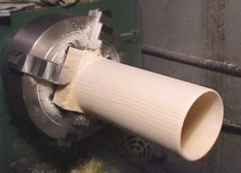
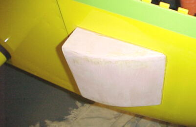
A boundary layer type air scoop was machined up from solid pine and bonded to the lower rad inlet hole in the cowling. This should decrease turbulence and drag considerably.
A new turbine outlet pipe was fabbed up and ceramic coated. This now exits roughly parallel to the airflow from the main lower cowling air exit. We hope to gain some thrust and reduce the plume drag over the older system which exited through the lower cowling at a 45 degree angle to the local airflow. The cowling is now easier to install also. Note stainless heat shield on belly skin.

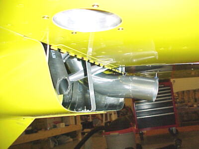
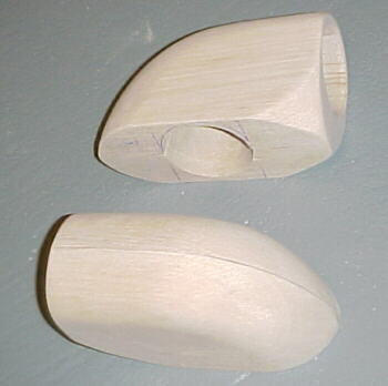
Twin intercooler discharge fairings were carved from balsa. These turn the airflow 90 degrees with low flow losses and exit into a low pressure zone. These should reduce drag and turbulence considerably over the temporary sheet metal exits previously fitted.
New cowling air exits were fabbed from balsa and glass/epoxy. These direct air straight aft out of the exit ramps and should improve the airflow exiting over the sheet metal ducts.
A UMA analog tachometer replaced the u/s chronometer to allow more precise power settings.
A few flights will confirm the performance of these mods, then the lower cowling will be repainted.
03/21/04
We did a few short cross country flights to check various systems and mods. Most of the things we played with now work. We found the power off descent rate at around 750-800 fpm with the power at 10 inches and 3000 rpm and around 80 knots. This means the glide ratio is about 10 to 1 which is a nice round figure. The EZ Trim altitude hold seems to work well, holding the altitude within 30-40 feet with no adjustments to the default settings. The Navaid gyro/wing leveler needs further setup as it does not hold the wings level or track the GPS properly yet. We experimented a bit with power/rpm settings. At certain rpms, there is a fair amount of vibration however, slight changes in rpm make the engine/redrive/prop combination very smooth. We found it very nice at about 4050 rpm and 26 inches at 6500 feet giving 136 knots TAS and 50 lbs./hr. fuel burn.
I'm not very happy with the landing gear characteristics on touchdown down to about 30 knots. The aircraft bounces and bounds a lot if it hits a hollow in the runway and I've encountered nosewheel shimmy several times now. It is bad enough that it has damaged the nose wheel fairing due to the extreme deflections. The temperatures and pressures seem to be in really good shape now. Water temp never exceeds 90C in the climb and pretty much sits at 85-90C in cruise with the heater off. It will immediately fall to 61-70C if the heater valve is even cracked open. Cowling pressures with the composite exits are similar to those with the temporary metal ducts although the new intercooler exits won't be installed until they are painted with the cowling this week.
03/29/04
We got the cowling repainted with most of the new ducts in place now. Thanks to Dillon at Klarenbach Aviation for the sanding, filling and painting which I had no more patience for. We did a trip up to Rocky Mountain House airport to shoot some T&Gs. Cruising at 10,500 feet at 25 inches and 4200 rpm, we showed 143 knots TAS on 50 lbs./hr. We had the pleasure of having the airport manager formate on us in his Harmon Rocket over the airport to check each other's plane out. Unfortunately radio reception was not too good so I didn't have time to snap a photo. Next time. We tested the Navaid wing leveller and GPS units plus the altitude hold. All seem to work now.
03/31/04
We did a short flight at +20C to test cooling. Intercooler discharge temperatures were around 40C in cruise which are not acceptable so we'll have to continue to work on that. Coolant temps were up above where they were at cooler ambient temperatures but all ok, never exceeding 90C in flight or on the ground.
04/02/04
Did a short flight with the intercooler inlet scoop wired with a thermistor to verify that no hot rad air was entering the scoop causing high intercooler discharge temperatures. The temps were the same as ambient so it would seem that we don't have enough exit area on the intercooler yet. Tests with the new exit ducts below show no gain in pressure differential over the sheet metal duct but drag should be reduced.
Intercooler Pressure Differential vs. IAS at 6500 Feet With New Twin 2.5 Inch Outlets
| IAS Knots | Inlet Press | Outlet Press |
| 110 | 3.9 | 1.9 |
| 115 | 4.2 | 2.0 |
| 120 | 4.6 | 2.2 |
| 125 | 5.0 | 2.4 |
04/15/04
We've now switched the coolant from a EGW mixture to non-aqeous Evans NPG+ propylene glycol with a 375F boiling point and vapor pressure 60 times lower than water plus lower surface tension. We hope this will alleviate the many problems we have been having at higher ambient temperatures. This coolant can also operate with a no pressure cooling system, increasing reliability. Preliminary ground tests seem encouraging. After running the engine at idle for 18 minutes with no fan on, coolant temp did not exceed 58C which is much lower than before under similar +8C ambient temperatures. We've also added an additional intercooler outlet hose from the discharge plenum to try to increase flow through the core. Flight testing will soon validate these changes.
04/19/04
We conducted a short test flight overhead of the airport to check things out with the Evans coolant. Temperatures seemed fine for most of the flight however water pressure spiked to 23 psi in the climb which should not have been possible with a no pressure cap. Not sure what was happening here but I believe the gauge. Coolant temp in level flight was varying between 70 and 90C with about a 35-45C drop coming out of the rads. When I opened the heated valve fully, ET dropped from 90 to 80C but a couple of minutes later with the valve closed again, ET hit 110C. A few minutes later, we noticed a coolant smell and saw some moisture on one corner of the windshield. We started down for landing and I noticed that the heater air started getting colder which indicated low coolant levels. I pulled the power way back and angled in for landing as quickly as possible as the oil temp was up to 115C. We pulled the aircraft back to the hangar and saw that there was a lot of coolant on the belly. After examination, it was found we only had about 2-3 liters of coolant remaining, meaning that around 2 liters had gone overboard. The Mobil 1 synthetic oil had kept the engine going. We'll have to do a further engine examination including compression check before returning to testing.
One positive thing from this flight test was the third intercooler discharge hose brought intercooler effectiveness up to 64% in cruise which is about 10% bettter than before. The hose was exiting into the cockpit so I could actually feel the temperature of the exit air and pressure in flight. Pressure measurements showed the same net differential as with 2 exit hoses but lower inlet pressure, likely meaning than less air was damming up in front of the core.
After some thought on the coolant loss issue: Why did the pressure go to 23 psi? Did coolant start to vent overboard during this time? Why was the coolant dumping if it never got within 60C of its boiling point? What caused the temps to spike up to 110C? I arrived back at the thermostat arrangement on the EJ22. This is located upstream of the water pump inlet. Two .125 inch holes are drilled in the thermostat to allow water flow at all times. A .1875 hole restrictor is in the bypass hose that carries water from the left head and turbo into the thermostat housing. The heater core discharge exits right at the thermostat bulb. I surmise that opening the heater valve allows a large slug of cold coolant to hit the thermostat bulb and shock it closed. Because of the small amount of bypass water through the restrictor, and the mass of the thermostat bulb, the thermostat is very slow to open, meanwhile the coolant is heating up in the engine and not going through the rads. A similar thing happened in early winter testing when the heater valve was opened. In light of this theory (of which I have had many), I will return to a pressure cap, remove the thermostat and close the bypass completely. Lots of ground testing will preceed flight testing.
Below: Revised lower rad inlet, intercooler exits and intercooler inlet with cowling side air exits.
04/20/04
The engine has checked out ok with reasonable compression and no metal in the filter. After some further thought on the cooling issue, I think that not running a pressure cap is a mistake as the size of any air or vapor bubbles will be larger than with pressure on the system perhaps leading to poor conduction and more fluid displacement.
04/30/04
After 1.7 hours of ground running, we saw no problems. The engine can be run for 30-60 minutes with the fan on in ambient temperatures of +15C without overheating. This was with the Evans coolant, no thermostat, plugged bypass hose and a 7 psi cap.
We conducted a test flight with 4 water temperature probes fitted. These were located in various places to try to judge what was happening with the coolant flow. The results were somewhat puzzling although no coolant was lost into the recovery tank and the engine did not over heat. In level flight, the main coolant temp sensor fluctuated between 70 and 110C for no apparent reason. This was with the heater control off. With the heater valve open, coolant temp dropped to 70C and stayed quite constant. In the descent, power off, heater valve closed, coolant temp climbed to 110C again???
The chart below shows the various coolant temperatures in different parts of the the engine with the heater valve open and closed. ET is main coolant temp measured in the top coolant manifold from the engine, ET2 is another probe located about 6 inches further upstream in the same manifold, OT2 is in the water pump body where the header tank feeds the water pump inlet, WT2 is in the header tank after the coolant has passed through both rads.
| Parameter | Heater Off | Heater On |
| WT2 | 53 | 59 |
| ET2 | 110 | 70 |
| OT2 | 81 | 96 |
| AT2 | 105 | 65 |
ET and AT2 should read close to the same although the sensors have different resolution. They are close here. I can only explain the lower WT2 by the fact that delta T is higher here and more energy is being sunk off through the rads because of it. I cannot explain the correlation in OT2 which is in the thermostat housing. I can only surmise that there is some sort of vortex forming in the water pump inlet as the coolant exits the inlet hose into the pump body with no heater core flow. The heater core flow enters the pump inlet at 90 degrees to the main coolant flow. This may be adding turbulence to break up the vortex and aids cooling somehow. Or perhaps the pump is cavitating from lack of inlet area and the 3/4 inch inlet hose but is ok with the extra 5/8 heater hose flow feeding it. In any case, the engine temperatures generally drop substantially and are more stable with the heater valve open. This is out of proportion with the amount of air flowing through the heater box vs the two main radiators. A further flight with the heater valve open for the whole flight will be done next. Interesting!
05/02/04
We conducted a flight with the heater valve 3/4 open. ET in the climb stayed at 90C at 80 knots and 35 inches/ 4500 rpm. Ambient temp was 15C. In cruise, ET settled at 70-80C and was stable. We tested the pressure on an aft facing belly scoop as a future place to locate the third intercooler air exit. This showed -0.5 inches H2O so should be a good place for this. Plans are to place a third radiator in the lower right cowling to be fed from the right oil cooler inlet opening. This will use the normal bypass hose connections and should produce similar results to what was seen on this flight.
05/09/04
We flew about 45 minutes of circuits with the heater valve half out. Ambient temperature about 15C. Coolant temperatures were predictable, about 80C in the climb, 70C in level flight and dropping to 61C usually during the descent and touchdown phase. Oil temps would increase up to about 100C in the climb, decrease to about 94-96C in level flight and decrease down to 89-90 in the descent. We are awaiting a barrel type intercooler core which will be used as a coolant radiator, plumbed into the bypass hose circuit. This should allow similar coolant flow to the open heater core circuit without baking the occupants and increase net cooling at higher ambient temperatures.
05/13/04
Several flights over the last few days in the circuit at ambient temperatures ranging for +2C to +15C have shown the coolant and oil temperatures to remain stable and predictable in repeated climbs. These flights were all done with the heater valve half open. One flight was in light rain showers. We saw some interesting water patterns trapped in some low pressure and turbulent zones. The windshield/canopy junction was dry. A very slight leak was evident from the rear canopy skirt area.
05/20/04
I've been concerned with the seemingly high turbocharger compressor discharge temperatures on our Subaru installation so I instrumented our turbocharged Nissan 240SX development car to see what was typical on a known efficient setup. This revealed that the aircraft installation was fairly similar although the intercooler on the Nissan was more efficient due to packaging and intercooler core volume. I saw a compressor discharge temperature of 45-50C cruising at 3000 rpm, no boost, ambient temperature was around 15-20C. At a maximum boost of around 40 inches Ab, I saw around 70C. If the engine idles for a long time, the temperatures climb to 60-70C. The intercooler effectiveness was calculated at around 83% which is quite good for the 8.5 x 12 x 3.5 Spearco core. The engine is equipped with an H3 compressor. The best effectiveness measured so far on the aircraft is 62% but we have not completed full testing with the revised third intercooler discharge duct. I see substantial conduction of heat from the bearing center section to the compressor backplate and into the compressor air. Thermal barrier coatings or a stainless steel backplate might reduce this conduction substantially. The current aluminum backplate is a poor choice of materials here in my view due to its high thermal conductivity. This would be another place to improve power and altitude performance. Perhaps additional airflow directed at the backplate would drop temperatures as well.
05/24/04
The new radiator finally arrived. This is made by PWR in Australia as a water to air intercooler. It is a barrel shaped design with 2.25 inch inlet and outlet, 4 inch diameter core, 6 inches long with a total shell length of 12 inches.
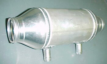

We're running the bypass hose water from the left cylinder head, through the turbocharger center section, into the heat exchanger, then out to the water pump inlet, right beside where the heater core oulet exits. Hopefully this will duplicate what happens to the water flow when the heater valve is cracked open. Air for the heat exchanger is ducted from the right oil cooler inlet through a PVC S-bend, through 2.25 inch SCAT hose. Air exiting the core is directed out the belly extraction duct.
05/28/04
The latest flight test with the new rad in place still showed that the problem was not solved. Unless the heater valve was slightly opened, coolant temps continued to climb from 70C to 110C. Our next action will be to instrument all 4 heat exchangers with temp sensors to measure the air exiting each core. We hope to check the effectiveness of each core in this way. I surmise that water flow may be inadequate because the current rads are plumbed in series offering higher resistance to flow and less energy dissipated because of lower delta T in the second rad. If the temperature studies confirm this, we may try to re-plumb the rads for higher water flow.
This flight quantified the intercooler effectiveness with the final duct configuration as follows at 6500 feet:
| Power Setting MAP/RPM | Intercooler Effectiveness |
| 22/4000 | 64% |
| 25/4200 | 60% |
| 30/4200 | 56% |
Effectiveness drops off with increasing engine mass flow through the core which is to be expected, despite higher mass flow through the inlet ducts and core.
05/29/04
Testing today reveals that the main left radiator is not dropping the coolant temperature as it should. The chart below shows the air exit temperature behind each heat exchanger. Ambient temp +5C, coolant temp 76C. My only guess at this point is that the coolant is moving too fast through the first core to have the heat removed. It is slowed substantially through the first and second cores where heat transfer is more effective. Next thing to try will be to split the coolant flow to try to reduce water flow rates through the first cores, reducing coolant velocity and hopefully aiding heat transfer.
| Heat Exchanger | Air Exit Temperature |
| Left Front | 39C |
| Barrel | 54C |
| Heater | 70C |
| Lower | 62C |
The hotter the air exit, the more effective the heat exchanger is. The lower rad receives pre-cooled coolant from the main left rad so it is probably highly effective. The barrel cooler receives coolant from the hot left head and the turbocharger center section. It appears to be moderately effective. The heater core is very effective with air temperature within a few degrees of the coolant temperature. This may explain the major effect heater core flow has with dropping engine coolant temperature. For some reason, the air exiting the main left rad with the highest delta T between ambient and coolant temp shows the lowest rise in air exit temp.
06/01/04
A reader, Doug Dempsey, had some insights into possible problems with regards to cooling in our present configuration. His feelings were that most of the problem may have its root in flow separation inside the radiator ducts. Indeed, at one point when I had K&N breather filters on the crankcase vents and some oil mist was coating the engine, a small about of oil would collect on the outside leading edge of the left air inlet. This was probably caused by serious flow separation creating a very low pressure area here. If so, it's likely that only about half of the left rad is being effectively wetted. Last night I installed a guide baffle with zero divergence to seal the cowl inlet to the rad core face. The test flight showed very little change in temperature (a slight rise) despite having only about 1/3 of the core exposed to unseparated airflow so we might be on to something here. Next plan is to install a guide vane set into this inlet to control separation and testing again.
06/06/04
I instrumented the main radiator outlet tank with a temperature probe to check the delta T across the core. Flight testing showed NO temperature drop, indicating a serious airflow problem through this radiator. For reasons that I can't explain, the engine stayed cool in cruise flight at +18C ambient temperature for the first time with the heater valve closed. It just sat at 80C even with the power up at 30 inches and 4200 rpm. It would appear that the lower and barrel rads are capable of dissipating enough heat to stabilize temperatures without any help from the main rad. The next flight will measure the effect of a revised inlet shape on the main rad duct. This uses a 5 degree divergence angle to expose about 28 square inches of the heat exchanger surface to airflow, hopefully without creating turbulence. Other steps may include taping over the main rad inlet to absolutely verify its lack of effectiveness and measuring aft fuselage pressures and temperatures under the belly for possible relocation of the rad into this area.
06/08/04
With the revised left rad inlet, we saw little difference in coolant temps. Pressure measurement of the aft fuselage interior showed +0.5 inches of water pressure and belly temperature was about +9C over ambient indicating that this area might be a good location for an aft mounted radiator. Temperature measurements of the rad inlet and outlet are inconclusive at this point so additional temperature probes need to be placed there for a definitive answer on rad effectiveness.
06/09/04
With new temp sensors epoxied to the inlet and outlet rad tanks, flight testing showed a 21-24C drop across the rad which makes more sense. The earlier readings were invalid. The engine cooled fine in cruise flight with the heater valve closed again. Ambient temp was 15C on the ground and 8C at 6500 feet. I can only surmise that we had air in the system as when I went to install the internal temperature probe in the left rad, about 1.5 inches of air was trapped in the top of the rad. I topped up the rad through the probe hole and everything ran properly cool from this point on. We need to test in warmer ambient conditions to make sure everything is well. Plans are also to add air cooling to the compressor backplate and oil pan to reduce induction and oil temperatures respectively.06/13/04
We've now flown the aircraft several hours without having to open the heater valve to keep the engine cool. Temperatures are stable and predictable so it appears that we have a workable solution at this point at least up to 20C ambient temperatures. Performance testing will be the next phase concentrated on.
07/03/04
With oil temperatures becoming a concern in the climb on warmer days, we were forced to add an additional NACA duct for the turbocharger induction air and use the existing duct under the spinner to funnel cooling air to the oil pan. This dropped pan temperatures 20-30C and it would appear that we are now good to go now for up to +25C and extended maximum climbs.
09/13/04
I ordered some intersection fairings from Aero Strategies Unlimited who I highly recommend. They are honest and their work and service is top notch. I taped these in place after doing a baseline run without them at 8000 feet and 4600 rpm and 30 inches. Looks like these are worth another 2-4 knots so I will be finishing them for permanent addition later this year.
10/25/04
We installed an engine thermostat for winter flying but experienced some of the same coolant temperature spikes as last year for reasons not understood. We'll be removing the thermostat and installing a cable controlled rad inlet door to keep temperatures stable.
11/13/04
I've added the cable controlled rad inlet door now which covers about 50% of the main radiator area. This speeds warmup in cold weather and keeps coolant temps up in flight with the heater on.

01/07/05
The aircraft is currently down for maintenace and upgrades. Wheel pant/ main gear leg intersection fairings are being added and a stainless steel turbocharger compressor backplate will be installed to try to lower compressor discharge temps through lower conduction rates from the center section and turbine housing.
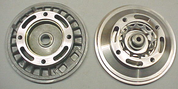
Factory Garrett aluminum backplate left, stainless steel custom backplate right
Upon disassembling the turbo, I saw that it was in excellent condition with no coke deposits. The Decalin TCP lead scavenger seems to work nicely as there was just a light dusting of lead and combustion deposits of a pink, tan, white color on the turbine wheel and housing which was easily rubbed off.
01/14/05
We have fitted the aircraft with a WMS wideband air/fuel ratio monitor to precisely measure mixture vs. EGT. We'll report these findings in this area once test flying is complete.
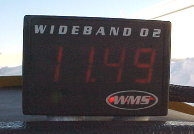
Initial testing showed a hot idle AFR of around 13 to 1, WOT on runup of 11.5 and cruise with the mixture at 0% of 12 at 25 inches and 4200rpm.
01/20/05
New fairing were fitted. We hope to measure a speed increase with these in place.
Leaning experiments with the WMS wideband meter were carried out in some very rough air at 4600rpm and 27 inches:
knob at 0% EGT2 1301F, AFR 11.7
knob at -5% EGT2 1336F, AFR 12.4
knob at -10% EGT2 1372F, AFR 12.9
knob at -13% EGT2 1411F, AFR 13.2
We hope to test leaner mixtures in smoother air soon. If the engine will run happily at 14-14.5 to 1 AFR, we'll see fuel flows drop well below those of a comparable Lycoming engine.
02/07/05 A Forced Landing
On January 22/05 we were conducting leaning experiments with the WMS wideband AFR monitor and turbocharger compressor temperature measurements with the stainless backplate installed, on a flight between Springbank and Vulcan at 9500 feet. As we leveled off, it was noted that the electronic digital altimeter was changing readings 20-40 feet randomly. This was attributed to rising/ descending air initially. Within 2 minutes, the fluctuations were 100-300 feet but the air seemed smooth. About the same time, I noticed that the WMS meter was reading completely wrong yet the engine was running perfectly. A few seconds later, the GPS went offline. It was recycled but died again within 20 seconds so I shut it off. When I scanned the engine instruments, I noted that the tachometer was reading incorrectly and the Navaid gyro was indicating a right turn when we were not turning. I suspected a charging system failure immediately and checked the battery voltage in the SDS monitor. This read 9.5 volts so I knew then that we had a charging system failure. At the time, I was not worried about making it to an airport, assuming that the alternator had failed just in the last few minutes and believing that I had 20-25 minutes of battery power remaining. In fact, it is likely that the alternator failed soon after takeoff from Springbank but I did not notice signs of the failure until the battery was well over half dead.
Calgary Terminal called to clear us from his zone but his transmission broke up. We could not respond and shut off both comms and squawked 7600 for about 30 seconds before the transponder went down. I shut off all other non-essential electrical loads at this time. I estimated Vulcan airport at 12-15 miles away which we were heading straight for. About 4-5 minutes later, the engine started to run rough as battery voltage was down to 6.5 volts. 2 minutes later, the engine started to cut out intermittently. By turning the low pressure fuel pump off for 15 seconds at a time, partial power was restored for a few seconds. One minute later, the engine essentially ceased running but the prop was still windmilling. I settled on 90 knots as a glide speed with the VSI around 1000 fpm down. About 3 miles out, our altitude looked fine to make the runway, high if anything. 1.5 miles out and it was clear that we would not make the runway. I was worried about 2 ditches, a road and a man made waterfowl dugout off the far end of the runway and did not want to arrive high as we had no flaps. This turned out not to be a problem as we would be well short of the threshold. I made a shallow turn into wind to land in a field parallel to the plowed furrows. Airspeed bled off rapidly in the turn and I had to keep pushing the stick forward to maintain 65 knots. The deck angle was somewhat scary. Don't stall! don't stall! was going through my mind vs. the alarming deck angle. At about 20 feet up, I initiated the flare. We touched down level or slightly nose down as there was insufficient stick and energy to complete a proper flare. The nose gear gave way, then the prop and there were some expensive crunching sounds. We slid to a stop on the partially snow covered/ frozen field in about 200 feet.
The G meter read 7Gs from the vertical impact. I used my cell phone to contact Edmonton ATC and report the forced landing. As there were no injuries, we were authorized to move the aircraft by Transport Canada. The local police, EMS and fire services were extremely helpful and efficient. They even arranged for a nearby trucking firm to recover the aircraft for transport back to the airport. Joyline Transport did an excellent job organizing a cherry picker and lowboy at both ends, arranging all permits and getting VZX back to its hangar. Many thanks to all involved from the Vulcan area including manager Wally Walpole, Ken, the talented lowboy driver, the field supervisor and "Woody" from Lethbridge, an interesting personality to be sure. These people made Vulcan the nicest place to have a forced landing and the best of a not so good day.
Preliminary investigation showed that the alternator field fuse was blown for reasons undetermined at this point although some swarf was resting on top of the fuse holder in close proximity. Whether this was the cause or simply dislodged from the impact will probably never be known. We'll be performing tests on the charging system when the aircraft is repaired again. The impact sheared the nose leg retaining bolt clean off. The leg punctured the stainless firewall and battery box and came to rest against the battery case. The nose leg was completely "pretzelized" with the tire ending up flat under the cowling. The main gear legs were both bent back an extra 10-15 degrees and the IVO propeller shattered 2 blades on impact. Various wheel pants and fairing were also damaged and both brake rotors were bent. No structural airframe damage was discovered and repair is under way. Thanks to Van's for designing such a robust airframe and I'm glad I was in a metal aircraft.
Lessons Learned and Applied
Thinking in hindsight on what was not readily apparent at the time of the emergency:
The low voltage warning light was likely ON for 10-15 minutes and remained unnoticed by me because I was busy recording AFR data. The warning light is not a flashing type which is much more likely to attract attention. A 95dB warning buzzer will now be added so that a charging system malfunction will be apparent immediately. I strongly recommend an aural warning vs. a light. The delay in me noticing the failure resulted in the forced landing. I believed that I had 20-25 minutes of battery power remaining when the failure was detected but had more like 10 minutes at that point. Commercial type aircraft employ an aural warning to alert the pilot and an annunciator panel to identify the fault. Why? Because this is a lot better than a light.
Pilots always talk of instructors throwing impossible multiple system failures and emergencies at them in training or in the simulator. Well, this time, we had such multiple, progressive system failures and did not recognize what was happening until the third device started giving odd readings. It is worth thinking about odd readings rather than dismissing them. You might save valuable time.
We rely so much on GPS but the "Nearest Airport" feature does not help much without electrical power and a dark screen. Having a map handy and marking last known position every 10 miles is not a bad idea. Glass cockpit advocates take note on the reliance of these on electrical power. We had no time to Mayday or really squawk a comm failure before power was lost. This could be serious in controlled airspace.
We had no battery backup as this was deemed unnecessary, thinking that the alternator failure would be immediately noticed and that I'd have 20-25 minutes of flight time to find a suitable landing spot or airport. A second 18 amp hour battery will be added with a separate switch, independent of the master solenoid. A backup battery will give you time to get the aircraft on the ground if everything else packs up and is your ultimate insurance. I was worried that the master solenoid would trip open at the low voltage, effectively signing everything off. Fortunately, the hold current required on these is quite low but this is an extra drain on the battery.
Most of the electrical devices were effectively offline at around 9 volts. Fortunately the SDS ECU and coil pack functioned down to the very last along with the fuel pumps, even at 6.5 volts where the battery is virtually dead. SDS has voltage compensation for the ignition and injector drivers which helped in this situation. Does your ECU have this?
Should I have picked a road or smoother field immediately rather than heading for an airport 20-25 miles away? Well, I would have if I'd known how bad the battery state was.
I should have pushed the throttle up and climbed to get as much altitude as possible to arrive very high OVER the airport but again, I thought I had lots of time.
With total power loss, the aircraft does not glide as well as it does even with idle power. The 3 blade prop has considerable drag due to its flat plate area. This is something you can't practice, but am aware of now. The deck angle to maintain airspeed is steeper than in training. Maintain speed at all costs and have a margin of extra speed for the flare as the elevators are less effective with no power. Train often for engine failures. It CAN happen to you! I'm glad that I did train fairly often. There was no panic and I did most things instictively.
Wear your shoulder harness! We always do but it is surprising how many pilots are injured or killed with them dangling by their shoulders. Have winter gear with you when you winter fly. We did, even though it was a pretty pleasant, sunny, winter day. Remember, it CAN happen to you!
Use all resources possible. If you have another pilot with you, hand some responsibility over to them for map reading, calling out airspeeds, altitude, reading emergency checklists, giving you flaps etc.
Damage will be repaired. Systems will be changed. Checklists will be altered and training will be intensified. I pledge not to forget the lessons learned here and am very happy to still be here to write this.
02/09/05 Compressor Changes
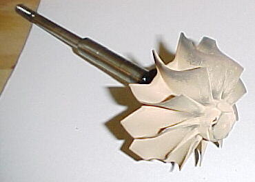
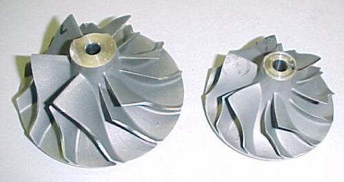
While the aircraft is down for repair, it will be fitted with a larger TO4E -50 compressor as the stainless steel backplate mod on the T3 compressor did nothing to reduce compressor discharge temps as expected. We hope that the higher flow rate and more efficient aerodynamics of this compressor will bring down our temps and add a bit more power at altitude.
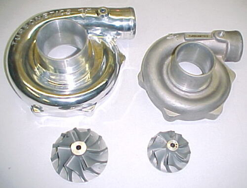
New TO4E- 50 compressor vs. T3 -Super 60 used initially
03/14/05 Alternator Problem
The aircraft is now repaired and I will start ground running and taxi tests soon. The second battery is installed now and I have checked the turbo scavenge pump for brush and bearing wear. It looks to be good for at least 300 hours or so. We have tested the alternator and found that the field windings in the rotor are open somewhere which explains the alternator charging problem. Can't see where. Can only speculate that failure was caused by excessive heat or vibration or both. The oil cooler dumps hot air directly aft into the alternator which can't be good for it. I've never seen a hard failure of this type of alternator in my many years of working on Toyota vehicles professionally but there is a first time for everything! Later, we discovered that the alternator we had been using was an aftermarket replacement and not a Nippon Denso part. This might explain the problems.
03/18/05
I ground ran the engine with the new ND alternator installed. I tested the backup battery system and aural warning system. Both worked as designed.
03/28/05
I did a test flight on the aircraft yesterday and everything seems to be functioning well. We'll be continuing the leaning experiments and compressor tests soon.
04/11/05
The E50 compressor was tested extensively up to 11,000 feet and is performing better than the S60 T3 compressor previously used. At a 1.73 pressure ratio, compressor discharge temps were down about 12C. Temps were more stable with less rise as the PR increased with altitude. At 7000 feet and 33 inches, INDT was 69C. At 11,000 feet it had only risen to 75C. No adverse effects have been noted with the new compressor and no surge is present under any conditions.
Leaning experiments were also conducted comparing EGT and AFRs using the WMS wideband. The engine was leaned to 14.7 AFR, -22% on the mixture knob, EGT2 was 1481F. The engine seemed to run fine. The knob settings correlated well with the AFR readout at various settings.
05/06/05
We have installed a new rad in the rear fuselage fed by a NACA duct in the belly. Air exits out new rear facing ejector ducts fitted underneath the stab on both sides of the fuselage. Pressure distributions were checked in CMARC and plotted in POSTMARC to find the best duct locations for this experiment. We'll verify finding with actual pressure probes in flight with the NACA dact and ram ducts fitted over top for comparison. This rad replaces the cowling mounted barrel rad added some months ago. This also provides a welcome shift in the C of G another 1/2 inch aft.
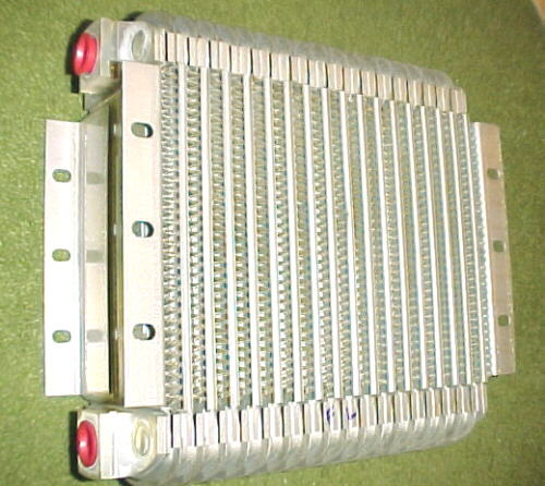
Aero Classics oil cooler gives 37 square inches of face area and 135 cubic inches of cooling volume
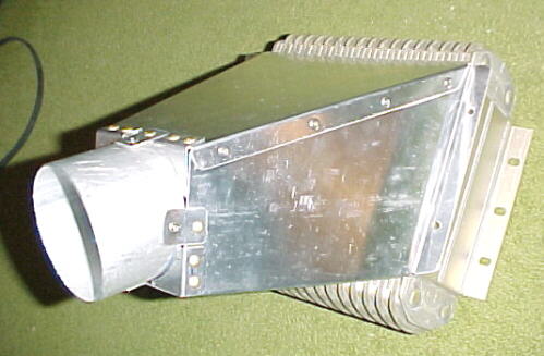
Aluminum diffuser attached to rad, fed by 3 inch SCAT hose
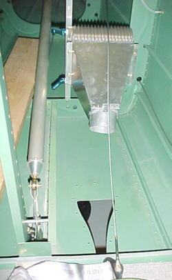
Assembly mounted in rear fuselage
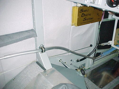
Nowhere else to run the 1/2 inch aluminum coolant lines. Nice hand warmers for winter flying!

Air exits out twin ejectors mounted under horizontal stab
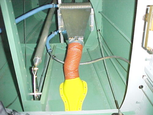
Complete assembly
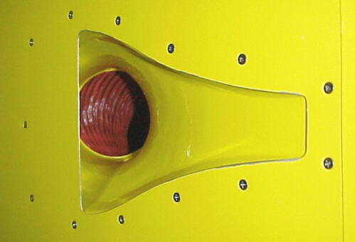
Belly mounted NACA duct feeds rad via 3 inch SCAT hose
It was a bear to get the air purged from the system with the new longer lines.
05/09/05
Flight testing of the new rad setup went well altough ambient temps were too low to tell how effective this mod will be. I took pressure and exit temp measurements. With the NACA duct only at 100 knots IAS and 5000 feet, inlet pressure was 2.5 inches of water, exit pressure was .5 inches in the rear fuselage. Exit temp from the rear ejectors was 34-36C so it is doing something back there. Ambient temp was 8C at altitude. I landed and taped on a sheet metal ram duct over the NACA duct to check pressure differences. This brought pressure up only .5 inches to 3.0 on the inlet. The NACA duct works quite well in this location on the belly.
05/27/05
Still not happy with the coolant temps in the climb on warmer days, I've now removed the Ford aluminum heater core/ rad from the nose scoop and replaced it with a 7 X 10.6 X 1.25, 2 core motorcycle rad. The Ford heater core I felt had a tube and fine spacing too close for proper airflow, causing high pressure drop. The SPAL electric cooling fan was mounted behind this and in hot idle ground running did nothing to reduce coolant temps so this has also been removed. Air to the new rad setup is routed via SCAT hose from the right cheek and the 3 inch scoop below the spinner. Some air from the 2.5 inch scoop under the spinner for the oil pan can also flow into this rad.
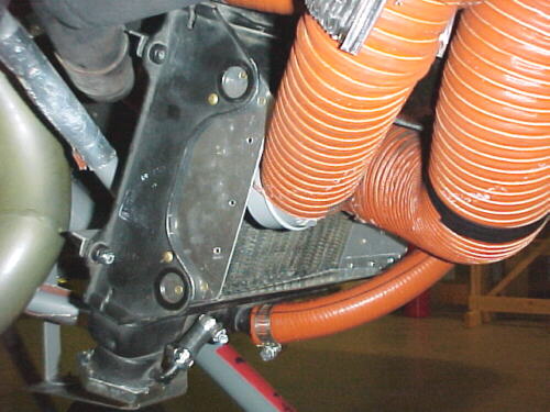
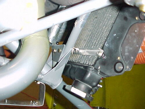
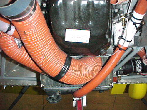
Shop vac was used as poor man's wind tunnel here to test airflow through various ducts and the new rad
05/30/05
Initial flight testing showed a fair drop in temps during the climb and cruise so I need to wait for a warmer day and do more extended climbs to verify this. Looks like we're on the right track here finally.
05/31/05
Another flight today at climb power from 4000 to 6500 MSL. Coolant got to about 210F climbing at 90 knots IAS. Ambient was around +13C. Now found out that the VDO coolant temp gauge is reading about 20F high so we are actually seeing more like 190F in the climb which is very satisfactory.
07/22/05
Been getting some crankcase vent fumes entering the cockpit through the belly NACA duct so I modified the crankcase vent system to move the exit over to the right side away from the duct. This seems to have helped a lot.
09/04/05
Tested a new boundary layer scoop for the rear mounted rad. This boosted pressure recovery to 4 inches over the NACA duct and cooling is a bit better in the climb on hot days. This will be made quickly removeable for the fall, winter and spring months where it's not needed.
10/02/05
The recent addition of a digital water temp gauge caused a serious engine miss which was traced to electrical noise entering the MAP sensor input cables to the ECU. This was observed as a spike to maximum manifold pressure and consequent over rich condition. This may have been present for some time, explaining an intermittent burp on occasion in the last 25 hours or so. The addition of the gauge, brought this to prominence, making discovery possible. The solution was to re-route the MAP sensor cables away from all other wires. Initially we had 2 sensors and an A/B switch on the panel. This has now been replaced by a single sensor, hard wired to the ECU. This eliminates several connectors, about 4 feet of wire and a switch, reducing fault areas and antenna length for interference effects. This is another case for keeping things as simple as possible. By adding a redundant system, the entire system was made LESS reliable.
01/16/06
While VZX was down for the annual, I made several mods to the cooling and ventilation system. Ventilation on warm days was poor as the air from the NACA ducts was routed throught he heater core first, causing considerable pressure drop. Secondly, coolant temps were unacceptable in the climb still on warm days. I've placed butterfly valves in the heater system now and two belly exits to be able to run air through the heater core and out the belly now for extra engine cooling. Additionally, the NACA ducts now pass cabin ventilation air right to the eyeball vents. The lower front rad has now been boxed in fully and is fed by twin SCAT hoses. The cowling barrel rad has been reinstalled, the rear fuselage rad has now got the boundary layer duct feeding it and i've added a ball valve to control water flow to these last two heat exchangers. Should know soon.
01/20/06
A short test flight yesterday indicated that cooling has been improved in the climb. Even without using coolant flow through the rear and barrel rads, temps dropped in the climb. Ambient was around -5C.
01/26/06
Flight testing yesterday confirmed that the rear rad cooling loop is effective. By closing and opening the ball valve, temperatures were effected within 30 seconds. The new belly exits for the heater core air proved effective in cooling as well. Ventilation is also improved. Ground cooling without any fans in the system now may not be as good as before but still adequate. Oil temps were up a bit predictably because the oil pan blast tube is now feeding the lower rad plenum.
01/30/06
Another flight test yesterday with everything open, 75-80 Knots IAS, 35 inches MAP saw coolant temps stay way down. OAT at 6500 feet was -3C. Coolant temps would fall to 58C in cruise with 23 inches MAP with everything open. This is too cold. With the rear and barrel rad water flow closed off, temps would stay at 61C. Still too cold with heater valve cracked open. Probably ok now for warmer temps.
06/27/06
The aircraft has now been flown extensively in ambient temps up to 26C. Cooling is good now with everything open (all coolant valves and air doors) coolant temps never rise above 90C in the climb at 35 inches and 4600 rpm at 90 knots IAS and above. Oil temps stay around 110C. In cruise at 26 inches/ 4600 rpm, water flow through the heater core can be shut off and coolant runs between 70 and 80C which is nice. Oil temp is around 96-100C, again, just right. In descents, the rear rad water flow must be shut off to maintain 70C coolant temps. Ventilation airflow for the human element is much better than before the recent mods were done. I'm finally happy with the coolant system performance. It's been a long grind.
05/16/07
Over the winter, I drained and flushed out the Evans NPG+ coolant and refilled with traditional 30% Prestone ethylene glycol and 70% distilled water. Under similar ambient temperatures and power settings, this resulted in an 8 to 10C drop in coolant temperatures so this question is settled in my view.
I also removed the oil pan to fix a slight oil seep. The engine has always run on 100LL and I used Decalin lead scavenger. Oil changes were done at 35-45 hour intervals and 211 engine hours had been accumulated. The oil pan showed zero lead deposits inside as did the other interior parts. I conclude from this that when using Mobil 1 oil with these change intervals and Decalin, lead deposition is not a factor.