

12/06/99 Errors on Rudder Parts
The manual states that R405 is to be made from .032 sheet. This is not correct. It is made from 1/8 angle stock. The manual also states that you need to make R410 as per the plans. On my kit, this part is already made for you and only needs to be trimmed. I see that the last update on the manual and most drawings was in 1996. These need to be kept current. The numerous oversights are annoying and a waste of time for the builder. Another word of caution to builders of QBs- make sure that you don't already have the parts that the plans call for you to make. You will be really mad if you take 10 hours to build something that the factory already made for you!
12/08/99 Yet More...
The QB manual refers to DWG PR-1 section A-A for details on the rudder stiffeners. This drawing does not exist in my plan set. This is actually detailed in section A-A of DWG Q7. Unfortunately, this detail and other dimensions on the drawing are not the same so you don't know which ones to believe. The text uselessly refers to the trailing edge offset to be the same as on the elevators which QB builders already have done for them and can't see inside anyway.
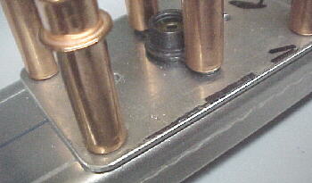
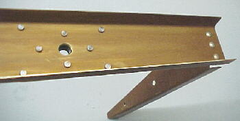
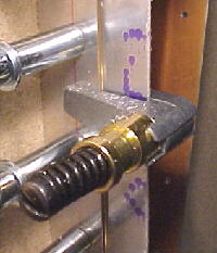
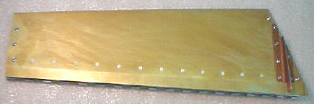
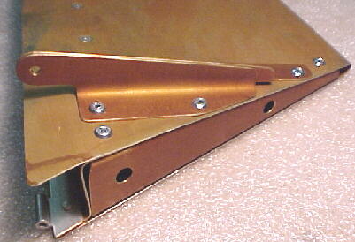
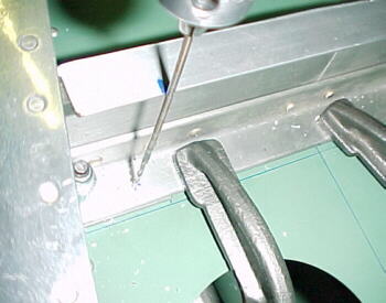
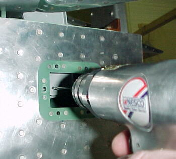
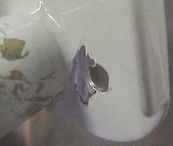
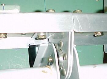
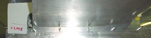
I built the VS-410 bottom, lower rudder hinge bracket from the .125 angle aluminum as described. Whoever designed this part probably forgot the extra thickness of this part over the 4130 brackets used in the other locations. Consequently, the pre-drilled rivet hole in the fin spar are too high. As can be seen below, the upper holes do not penetrate the flat portion of the bracket but are on the radius. Not the best for forming a rivet head on. Additionally the -8 rivets called for in the plans to fasten this part to the fin spar are not included in the kit just like the 2 rear canopy sill rivets were not.
12/13/99 Rudder
The QB8-9 drawing for skin stiffener placement could be a lot better. Why does this drawing show the rudder spar flush with the skin at the rudder base? This is not what the assembly looks like. There are spotty dimensions on laying out the exact cutout area on top of the rudder skin also. I also recommend shortening the top skin stiffeners another 1/8 inch as they will otherwise interfere with the hinge doubler and rivets.
The R-408 top rudder hinge backup plate, if made to the plans dimensions, is too wide and overhangs the spar. I suggest reducing the width dimensions about 1/16 top and bottom. Did the factory actually build an airplane using these drawings? Van's needs to label what is in each Q bag as well so that the builder can find the various small parts rather than guessing or having to look through all of their bins.
12/17/99
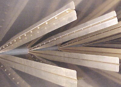
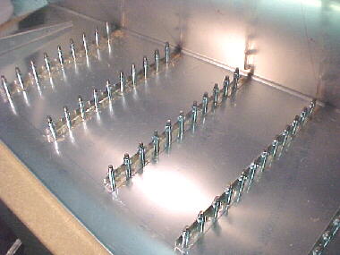
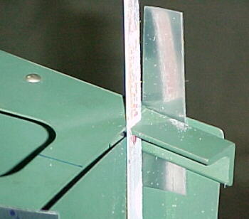
I got all of the rudder stiffeners built and alodined. The stiffeners and rudder skin were dimpled and back riveted. It is a little tough to do the last row but the job turned out well. Using the high tech bending brake device and the 1/8 wooden dowel depicted in the video, we completed the trailing edge bend on the rudder skin with good results.
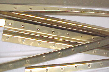
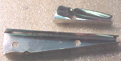
Alodined and dimpled rudder stiffeners
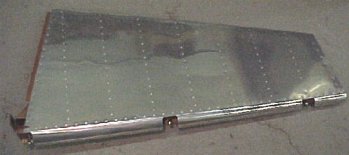
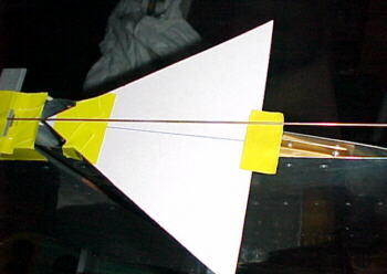
Inside rudder after completing trailing edge bend
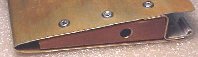
Rivet detail
12/22/99
Finally ready to start riveting the skeleton together.
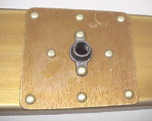
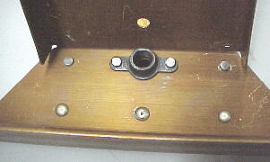
The parts were all alodined and we start. The plans ask to to refer to the drawings for rivet spacing and lengths. Most of these are given however there are none for the top rib R-403. Use 470 4-4 here. On R-407 and R-408 the plans call for 4-5 rivets. These should really be 4.5 so I cut all mine. Note that my kit did not include the -8 rivets for the nutplate on the base of the spar. I cut some -12s hoping that they were not all required for something else down the road. I could only squeeze a couple of rivets at the base, the rest had to done with the gun. So far, so good.
12/29/99
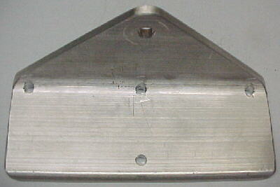
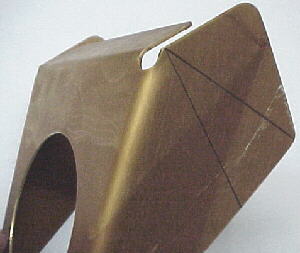
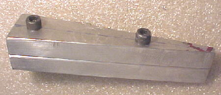
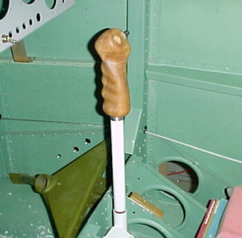
For some reason, the factory took great pains to shear the angles and form nice radii on R-410 so that it fits perfectly into the rudder horn angle. This makes one think that they wanted it this way. It actually should be trimmed on the second line to allow access to the rivets in the corner. The forward most rivet hole in the bottom rudder rib should be dimpled before riveting the R-410 brace on as this is VERY difficult to do afterwards. The wooden rudder jig depicted in the plans worked well and assembly went fairly quickly. Note that you need a vice grip type dimple tool to dimple the narrow ends of the ribs and a 4 inch squeezer jaw to rivet some rivets on the spar. There is no way to squeeze the rear most rivets on the ribs nor can you use the gun as there is no room for a bucking bar here. I had to put pop rivets in these areas.
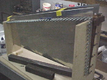
Rudder in wooden jig
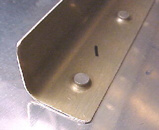
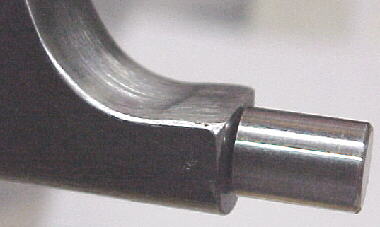
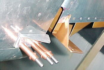
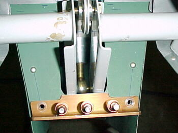
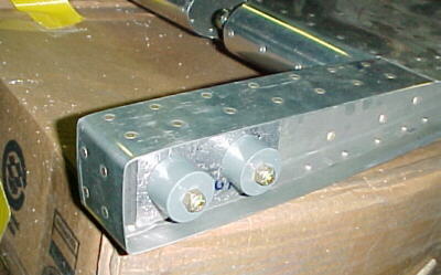
Rudder horn detail. Note different hole sizes.
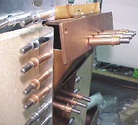
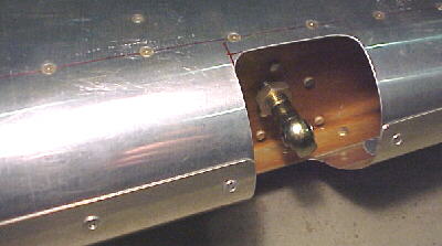
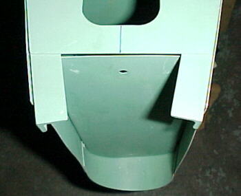
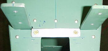
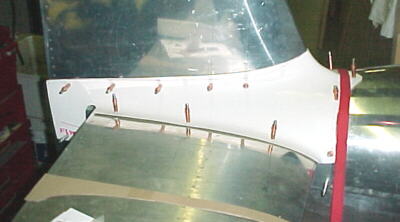
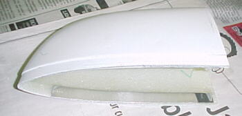
Fiberglass base fairing flange in position
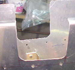
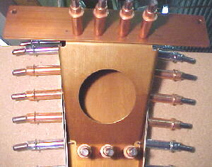
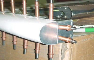
Rudder hinge cutout
12/30/99
I formed the LE radius after searching for 20 minutes through the preview plans to find details on this. As per previous experience, the QB construction manual makes no reference to drawing 6PP for these details. The preview plans all have NOT FOR CONSTRUCTION stamped across them, making one wonder if the details are up to date. In any case, these details belong in the construction manual and on a plans sheet with reference between the two. I have repeatedly had to refer to the preview plans for details not covered in the QB construction manual. This is poor in my view.
Another bit of wasted time was spent tracking down the AD-41-ABS pop rivets to join the LE on the rudder. You have to cross check the inventory lists to find these as they are labelled only as a Q bag. These bags need to be labelled with what they contain as well. On top of this, Van's did not include enough for the job so I have to find 2 more. I was impressed with how the top fiberglass rudder cap fit into the rudder. After all of the forming involved, this was a miracle.
12/31/99
I finished riveting the rudder leading edge so the metal structure is finally done. On to the dreaded elevator trim tab.
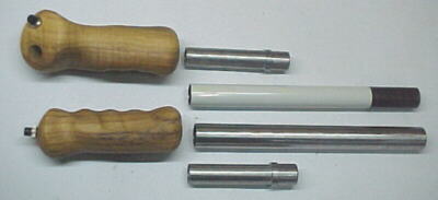
01/09/00 Elevator Trim Tab
After hearing horror stories about people screwing up multiple trim tabs and looking at Van's method of constructing these, I decided that the method depicted in the videos is far superior. This method uses separate end ribs rather than folding over the edges of the tab. Again, the manual is outdated and confusing. It is a mystery as to why drawing 5a is supplied at all and that the required drawing is labelled as a preview plan (pp). The video refers to certain clearances between the tab and elevator. After a half hour of reading everything in the manual and plans, I could find no reference to these. In addition, the manual refers to "the jig". It fails to mention that they want you to move one of the rudder jig V blocks to accomodate the elevator trim tab. I have shown this in the photos below.
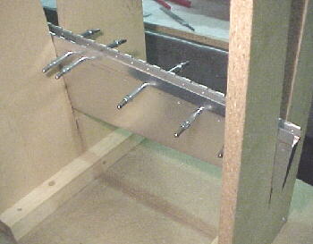
Follow the advice in the video. Take small cuts. The manual mentions that several types of trim horns have been used. Why not just cover the latest version? As it turned out, my horns were never shipped with the kit so I had to re-order them. I had them very quickly. Kudos to Van's for their quick support here. Once I got them, I realized that the building sequence needs a warning not to drill all of the spar/skin holes until after the horn parts have been positioned. As it luckily turned out, the one hole that I had already drilled was in the correct place. Anyway, the work is proceeding rapidly so far.
01/22/00
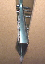
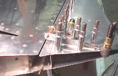
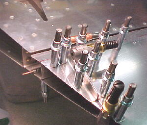
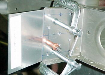
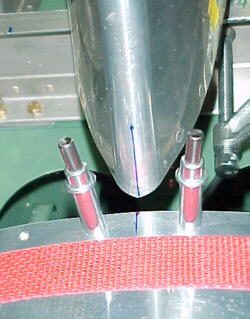
I drilled through the trim tab horns once I had drawn a line at 90 degrees to the elevator trailing edge, intersecting the center of the servo motor pushrod cutout, to line the horn halves up on. The 2 photos below detail this.
The last major fab step is to make the ribs to fit into the ends of the tab. I made two form blocks out of 1/2 inch 6061 T6 plate and threaded one end for 1/4 NF Allen bolts. I radiused one end for the bends on the belt sander. I should be able to make both ribs with one forming block as the angles are the same.
02/08/00
I formed the two ribs and fluted them to get them straight after forming the spar relief over a notched wooden V block.
Riveting the trim tab together looked like it might be easy. Because the spar on the inside row of rivets is bent at about 95 degrees, my Avery longeron squeezer jaw would not clear it. After some head scratching, I decided that I would have to machine down the jaw to clear. Think about this carefully before attacking a $100 jaw. I filed it down, then carefully polished a radius into it with a 1 inch flapper wheel. I radiused the corners as well.
By flexing the skin open, I could just get the squeezer in to do the job. I used the steel pop rivets to attach the horn and end ribs. The QB manual has a couple of useless paragraphs describing how to fit the elevator side hinge which is already done from the factory. Their steps about riveting the tab in the jig don't make much sense either.
04/27/01
Started to fit the stab and ran into several more inaccuracies on the plans. First, the plans call for an F611-E control stop/spacer to be attached just in front of the vertical pickups. On the QB, this cannot be done as shown as there is already an angle brace riveted here. I plan to attach a control stop on top instead. The "scale" plans show various overlaps of the control stops and the hole for the elevator control horns. None of these are even close to scale with the dimensions for the F611-E or F612-B.
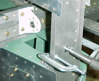
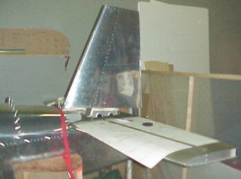
Another problem is that the top longerons project way past the structure and skin aft. No mention is made of cutting these off. Why didn't the factory do this before skinning. It is very difficult to trim these off now with the skins up against the longerons. Notice how crooked the rear bulkhead is in the photo. This is work performed by Van's people.
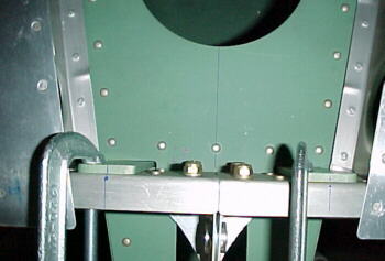
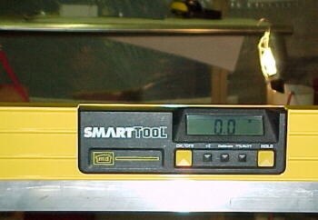
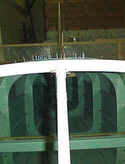
Careful alignment of the stab for squareness is accomplished with a digital level and measuring tape.
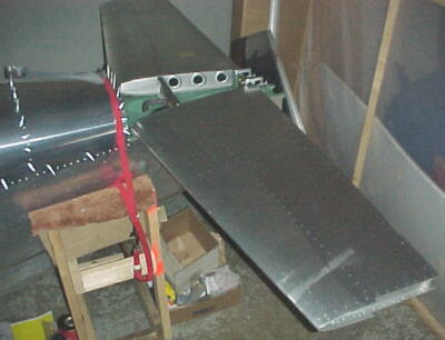
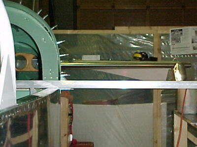
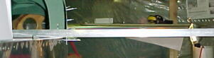
I checked the stab level every way possible. I clamped a piece of aluminum extrusion to the seat back brace and leveled with the digital level, extending it about 30 inches past the fuselage side. By projecting a light on the stab leading edge, it was possible to sight down this to confirm level.
04/29/01
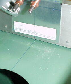
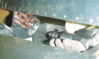
I clamped the stab in position and carefully marked the points to drill for the stab attachment. I used a level on the drill to put a witness mark on the upper spar to keep the drill vertical. I drilled to #30, then removed the asemblies and drilled to #12 separately.
I sawed off the projecting upper longerons with a hacksaw blade after placing protective shim material against the outer skin.
After much head scratching, it was decided that the fin's spar was about 3/4 inches too long and had to be trimmed. Nowhere in the manual or plans does it say this so I was wary. I cut off a 1/4 inch at a time until my other marks aligned. The factory riveted the F612 rear bulkhead on several degrees crooked which will tend to twist the fin's rear spar slightly. Nothing I can do about this.
04/30/01
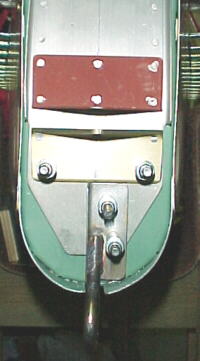
I drilled the fin spar splice plate to the spar.
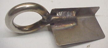
The tie down ring which is attached to the rear fin spar and F612 bulkhead was made incorrectly from the factory being 1.5 inches wide rather than the 1.125 called for in the plans. The ring was also welded to the opposite side from that shown in the plans. I had to trim this to clear the structure.
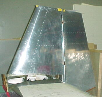
I projected lots of centerlines on all parts to aid alignment. On at the leading edge of the fin, spar and rear spar. I also sighted down the center of the roll bar brace, center clecos on the fuselage and fin to confirm. I also measured with a tape from the stab to the upper fin spar junction.
Once satisfied that everything was perpendicular and straight, I drilled the front and rear spars to the stab spars and clecoed.
05/03/01
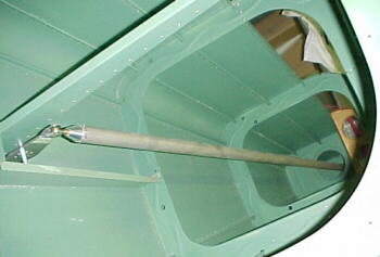
I fitted the elevators to the stab on the aircraft. The plans and manual are short on details as usual. I consider rigging of the control surfaces pretty important. About the only dimension given is that the rod end centerlines should be about .8125 from the spars. Other than this, you are on your own. I had to trim about .040 off the left counterweight structure to clear the stab. Once fitted, it was found that there was not enough up travel on the elevator as it hit the rear stop first. Also on the down side, there was not enough even with no stop, as the horns hit the rear spar structure. Not well designed. Anyway, I proceeded to fit the elevator pushrod tube to check for length. I clamped two pieces of wood over each stab/elevator junction to align the elevators. I clamped the front pushrod tube to align the sticks at 5 degrees forward from vertical as the neutral position and had the elevator bellcrank vertical. I marked where on the horn the rear rod ends should be and subtracted this distance from where it was. I machined off .25 inches and riveted on the aluminum end.
The elevator control horn center bearing support holes were next. I machined an aluminum bushing to fit into the 1/4 inch rod end. This had a #40 hole in the center. I used this to drill straight holes into each horn.
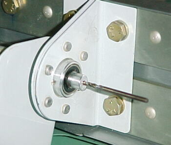
I then drilled the left elevator horn hole for the control tube on my mark to #30. Using a level and a square, I positioned the drill perpendicular to the horn and drilled through the left hole into the right horn. I then removed both elevators and enlarged these holes to #12. I also drilled out the center bearing support holes to .250 and ground the welds slightly to clear the bolt heads.
I hooked everything up and presto, the elevators can be moved with the stick. The stops just need to be adjusted for the proper travel.
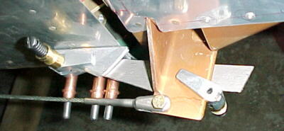
Next I started working on the rudder mounting. Again, no critical dimensions shown, not even the rod end centerline dimensions. I set these at .8125 on the top and middle ones and .750 on the bottom one because of the .062 doubler ahead of the spar. This seemed to work out ok.
05/06/01
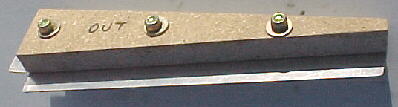
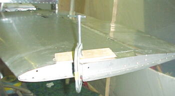
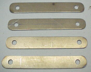
I built the rudder stops from the vague dimensions on the plans and a cardboard angle template which was taped to the top of the fin and rudder. This allowed me to center the rudder for installing the cables and to get the proper deflection in each direction. I cut the template to 31 degrees.
The final angle cut on the stops was marked by deflecting the rudder in each direction while holding the stop just below the rudder horn.
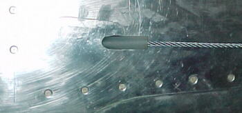
It was no surprise that there were more surprises on the plans. The plans have a dimension of 151.5 inches with an arrow going forwards into oblivion to mark where the hole for the rudder cable exit through the skin is to be drilled. 151.5 inches to where? I assumed that this was the firewall face. This proved to be incorrect as it did not agree with measurements taken on the plans showing this hole in relation to the F610 bulkhead. Was this 151.5 inches in a straight line or measured on the outside contours of the skin. No explanation. Why not give a dimension to a closer known point? I settled on 3.0 inches back from the rivet line on the F610 bulkhead. Van's poor job of installing the rear bulkhead crooked and F610 with a big curve on the right side made this more difficult to gauge correctly.
The next puzzle was how the 1/2 inch rudder cable ends were supposed to fit through 7/16 snap bushings. I decided that these had to be filed larger with a 1/4 rat tail file. All 18 of them.
05/07/01
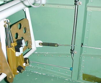
I clamped the rudder in the neutral position with aluminum strips and side grip clecos in order to string the rudder cable and determine the rudder cable link lengths. The cable exit holes were drilled and elongated for the protective sheaths.
05/14/01
After fitting the elevators, it was found that there was insufficient travel. The horns struck the lower stab spar so they had to be notched slightly. A front stop was built from .125 flat 6061 stock to limit travel.
The rear stop was found to restrict upward movement excessively so this was trimmed a full 3/8 inches from the dimensions in the plans. Deflections were tested with a digital level.
I machined adapters for the sticks and made both removeable for easier under panel access.
04/02/02
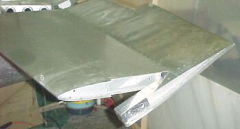
I fabbed the two aluminum fairings to fit under the stab and fit the upper fin/stab fiberglass fairing which does not fit very well despite a lot of work with the heat gun.
I bonded .025 aluminum strips on the backside of most of the fiberglass fairings to prevent the rivets from crushing the glass and pulling through. CS-4-4 pop rivets are used to hold these on.
I had to add a couple of steel weights to the lead counterweights already installed on the elevator containing the trim tab and servo motor.
I capped the elevator faring ends with .025 aluminum pieces.
11/26/02
Upon assembling the rudder and hooking up the clevis', I found that they bound on the rudder horn near full travel. The .560 specified for clerance in the drawing is insufficient. I had to increase this to about .625.