

The QB manual calls for the builder to make form blocks and 2 W-411 wing ribs. These are already built and clecoed in from the factory but nowhere has the manual been updated to reflect this. I spent half an hour trying to find out where these ribs were supposed to go and had to finally refer to the preview plans. Another waste of time which could easily have been prevented by deleting the section or putting a note in the manual. I am assuming that the factory makes these now on the newer kits in place of not pre-punching the wing skins as they used to. Drawing #20 does not show placement of W-411 either as mentioned in the manual. Drawing #10 has a complete top view of the wing structure showing W-411 in the tip location.
I drilled the W-411 wing tip ribs to the wings which went smoothly. Note that these are supplied with the QB kit contrary to the manual. Also note that the manual says that 2 holes are drilled in the rear spar to locate this rib. This is also not correct. Both the ribs and spars have all 4 holes pre-drilled from Van's. Next I went on to the aileron hinges W-413 and W-414. The rivet spacing in the plans would not work as the parts were 3/16 to 5/16 shorter than what the drawings specified. Another case of Van's not supplying pre-made parts which match their drawings.
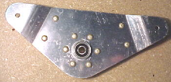
The QB manual states that holes are pre-drilled in the W-625 stub rib to which the W-413 is riveted. They recommend backdrilling through these holes. In fact, this is not correct either as there are no holes drilled here. The hinges should be drilled first and clamped, then drilled through the doubler, spar and W-625 rib from the trailing edge side. The W-413 and W-414 aileron brackets look very beefy except for the rather cheezy looking 3/16 bearings sandwiched between the layers. These are not replaceable and are very small. I guess that they work OK but something replaceable and with 1/4 rod ends would be better here.
03/05/00 Control Surfaces and Drawings, Avery Tools
Yes, we do say good things about people from time to time when it is deserved. I ordered some more tools and clecos from Avery Tools in Fort Worth, Texas and as always was very impressed with their service. This is the place to buy tools from if you are building an RV. You can contact them at:
www.averytools.com
The plans were reasonably clear on how to build the aileron bellcranks and these were finished in short order. Note the -6 rivet length given in the plans is not correct. These should be -6.5 to be technically correct. The bellcranks are well designed, being strong and light.
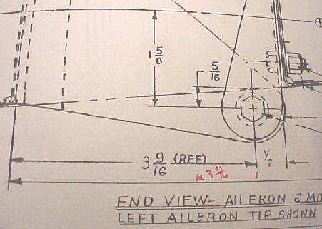
I built the airfoil templates as per the plans from 1/2 inch plywood however I did not drill the locating hole for the aileron pivot bolt as the plans and the dimensions do not agree. They are off by 1/8 of an inch. The plans call for 3 9/16 but when measured, is actually 3 11/16. You don't know which to believe.
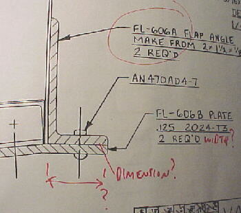
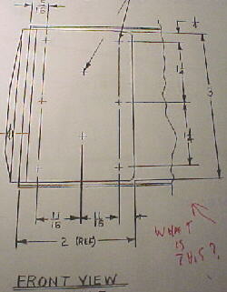
As I proceeded onto the other flap parts, I was again met by the usual lack of detail in the manual and plans. The manual needs to have a photo of complex parts like the FL-606 assembly to help the builder visualize things. I have done some drafting myself over the last 20 years but am by no means an expert. The first thing that I learned was that ALL drawings need to have the following information: identity of the part, viewing angle and scale. Dimensions for each part are also particularly useful I find. The RV plans often neglect one or more of these basic criteria, making them frustrating and confusing to use:
Lack of identity
I don't mean to keep harping on details like this. Van's has a well designed aircraft here that by all accounts performs very well however, I hope that they see fit to take the constructive critisism to heart and update their drawings and manual. All builders would appreciate it and enjoy the building experience more. It would save Van's lots of tech calls also. I provide this page to document some of the problems that I have faced and to help others by posting lots of photos to be able to see what things look like where the plans and manual may be lacking in detail. I hope that this is useful.
The outer aileron bracket doubler needs to be countersunk to allow the W-414 bracket to fit flush. The holes close to the upper edge of the spar must be done by hand due to the close proximity of the bend in the spar here.
One more thing to note that may save time, the manual refers to drawing 19 for some of the wing parts. This drawing does not exist in my plans set. There is a 19A which I assume is an updated version.
03/07/00
I ordered a couple of parts from Aircraft Spruce using their on-line system. This was easy to use and the parts were in my hands 3 working days later. Excellent service.
03/19/00
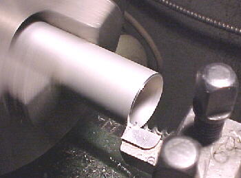
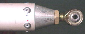
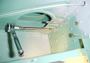
I got a reply within 2 days from Van's regarding the dimensional differences on their drawings, specifically for the aileron hinge point. 3 9/16 is the correct dimension but I don't buy the explanation that errors are due to drawing reproduction problems as some dimensions on the same drawing are dead on while others are way off. These are just poor drawings. While waiting for the reply, I had to move on. I built the outer aileron pushrods and trimmed the inner tubes to length. These jobs are clearly defined in the drawings and manual and straightforward. I trimmed and faced the tubing in the lathe to be sure that they were square. (08/12/03 As a note, when assembling the aircraft, I found that the pushrods were about .25-.35 inches too long and the machined ends had to be cut down slightly.)
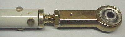
Completed outboard pushrod assembly
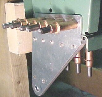
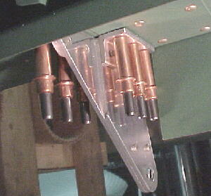
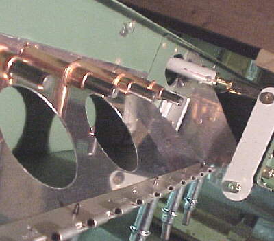
I made up a long 1/4 inch drill bit extender from tubing to drill the bellcrank mounting holes straight through from the top. The bushings were faced in the lathe. I mounted the bellcrank and pinned it in position as per the video.

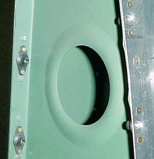
I moved on to the pitot tube assembly. I didn't much like the crude pitot tube parts supplied with the kit and had a proper heated tube already from a previous project. After some thought, I fabricated some mounting parts from 4130 streamline tubing and 6061 and drilled the mounting holes through the lower left wing skin just forward of the inspection cover. After screwing it together, I found the installation a little too flexy so I installed two skin stiffeners. This made everything nice and rigid.


I machined up a couple of holders for dimple dies to allow dimpling of the skin for the stiffeners. I'll use a hammer and two bucking bars to carefully dimple the holes.

03/21/00
The custom dimple die holders worked well. The holes were dimpled and the skin stiffeners riveted in place. The installation is complete except for painting the pitot mount and running the heater wires.


03/22/00 Warning on Wing Templates
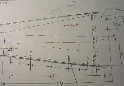
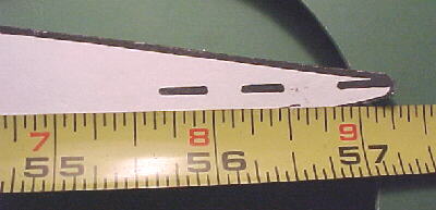
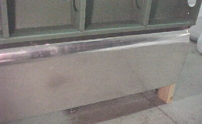
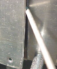
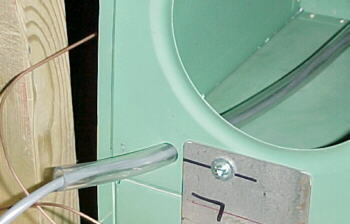
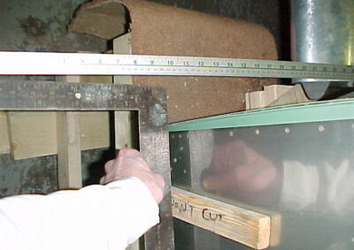
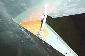
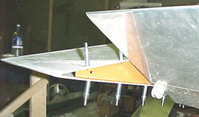
I spent about 3.5 hours carefully tracing out the airfoil shape from the full size template supplied with the kit and cutting and sanding the wooden templates to shape. These are used to align the control surfaces with the wing. I clamped the W-414 aileron hinge roughly in place on the outboard rear spar and clamped the wooden template to the wing to align the bolt holes on the bracket. To my dismay, they were off by over 3/4 of an inch! At this point, I didn't know exactly what was wrong. I tried to slide the aileron into the template but it would not fit. The leading edge of it was hitting the spar. I then measured the paper template. It was 57.25 inches long.
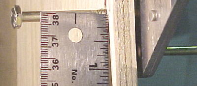
I then measured the actual wing. It was 44.125 from the LE to the rear spar.
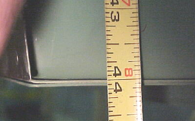
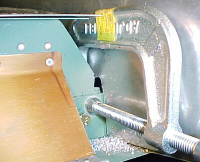
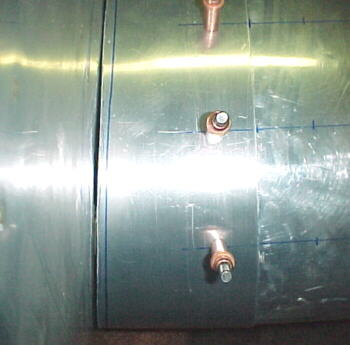
The plans state that the distance from the aileron TE to the rear spar should be 14 inches +/- .025. Plus or minus .025? How about .875? At least Van's has a sense of humour. I DON'T anymore. Given their plans dimensions, the wing should be 58.125 inches from LE to TE yet their template is 57.250 inches. This is nearly 1 inch different. As you can see in the photo below, there is a MASSIVE mismatch in hingepoint dimensions between where the 414 bracket hole is and the one on the template. The template also had 3/16 inch deviations in section profile as well in some places.
What can I say? I was really pissed off. 3.5 hours down the drain not to mention another 2 hours of head scratching trying to figure out what was wrong. After delivering thousands of these kits, Van's should be ashamed of errors like this. Every builder must have run into the same problem as me when they have gone to hang the control surfaces. Maybe it is time for Van's to actually update some of the 13 year old drawings and build another airplane using their instructions and dimensions supplied with the kit. If you did what they said, it would be a pretty funny looking airplane and the ailerons and flaps wouldn't move. Initially, I tried to measure the chord on drawing 10. It measured exactly 14 inches and has a 1/4 scale. 14 X 4 = 56 yet the actual wing is 58.125 in chord. Why even bother to produce drawings like this? Scale drawings are just that. You should be able to take a ruler, measure a dimension and multiply by the scale to get any full scale dimension. With many of Van's plans, this is a waste of time as they are either not to scale or dimensions are wrong.
03/23/00
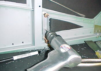
After much measuring using 6 plumb bobs, I was finally ready to drill the W-414 and W-413 aileron brackets to the spars. The manual has about one paragraph on mounting the ailerons. Not really adequate considering the importance of aileron rigging.
03/27/00
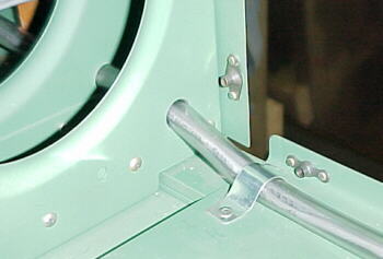
After clecoing the brackets in place and moving the ailerons, it was found that lower most rivet on the W-414 would hit the nose of the aileron at full up deflection. It was decided to install a flush rivet in this location for extra clearance.
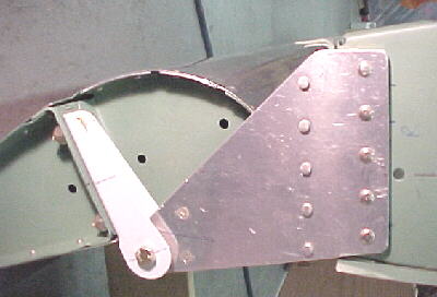
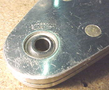
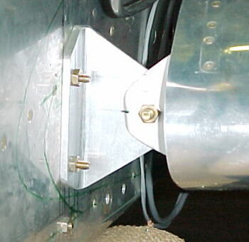
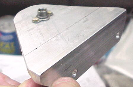
Outer hinge detail
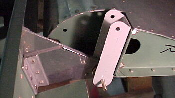
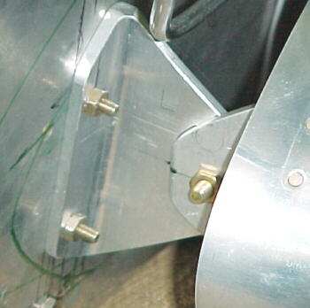
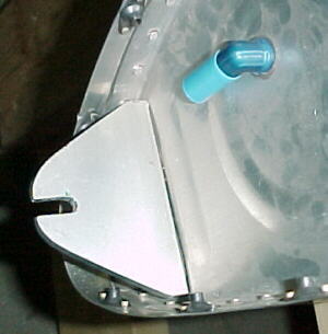
Inner hinge detail
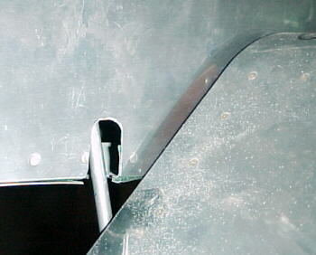
Right aileron hung in place...Finally
I noted another discrepancy on drawing 16, detail A. Right beside this is another view detailing the inner hinge. These two drawings have different details on the washer/spacer setups used. Which is correct?
03/30/00
I finished machining all of the spacers for the aileron hinges and linkages then cut the holes in the rear spar for the outer pushrods. I finished off the night by assembling the inner aileron pushrods. No surprises for a change on these.
04/04/00
I completed the fitting and riveting of the inner flap rib and brackets to the flap. It takes some thinking to be able to set all the rivets here due to the order, rivet types and sizes and leading edge curve of the flap. This turned out well.
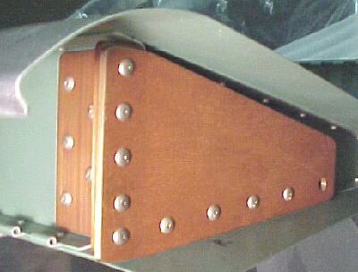
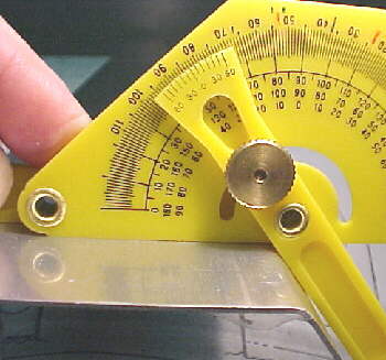
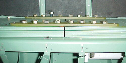
Going on to the the flap brace, I found the usual lack of detail in the manual and plans. Nowhere does it state the diameter to make the brace lightening holes and again the scale drawings are not to scale. I'll be making mine 2 inches. Also be very careful about orientation of the flap brace to the spar. The angles on the bends are not the same and they only go one way properly. This may not be completely obvious if you have had a long night and there are no warnings or orientation on the plans or in the manual. Measure the outside angles with a protractor. The one with the 45 degree angle rivets to the bottom of the wing skin and the 50 degree angle rivets to the spar. I have seen 2 people screw these up on RVs now so be careful.
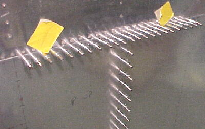
I have found more than a few unset rivets on my QB and some that are simply terrible. Check all the rivets that you can see and reset or replace the bad ones. I have found a lot on the wings and fuselage. The stabilizers and control surfaces by comparison have very nice work done on them.
These were some of the worst ones. Yes, they are supposed to be flush.
04/13/00
I fitted the right flap brace and hinge. This is not fun to do without the airfoil templates. Things lined up surprisingly well. I did have to trim the hinge slightly to clear the bend in the flap brace. You need to flatten out the inboard bend a few degrees where it meets the spar with hand seamers.
04/24/00
Before riveting, I noticed that both of the lower skins had small cracks around the holes where the cutout in the overlap portions were. I used a small rat tail file to remove the crack and radius the holes.
I squeezed all the rivets along the trailing edge of the wings and installed some of the pop rivets in the flap brace. Unfortunately the kit only supplies 30 of the required 48 rivets so I had to order some more from Van's.
05/03/00 Outer Wing Skins
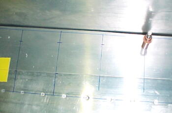
The wings skins as supplied by Van's were sheared very precisely. I measured and laid out the rivet spacing right on the skins. This takes nearly two hours per skin. They were taped in placed and drilled in a T pattern starting from the spar, outwards and downwards from the center.
It should be noted that the double scale detail "BB" on drawing 21, showing skin overlap detail is inconsistant with figure QB7-2, its text and the text on page Q7-3. Drawing 21 shows the outboard wing skin sitting on top of the inboard skin. This caused the usual head scratching, confusion and wasted time. The outboard skin actually slides underneath the inboard skin. Once this was established, it was simply a matter of LOTS of drilling, clecoing, deburring and dimpling as there are hundreds of holes here. The job turned out well and the wing is 90% done now, ready for the pre-cover inspection and final riveting.
11/07/01
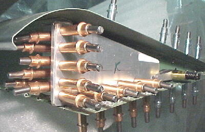
The manual has more mistakes on the riveting sequence on the wing, stating that "The last row to be riveted should be the row that joins the two skins just inboard of rib 63.5". There is no row of rivets just inboard of this rib. Did they mean outboard? Anyway it seemed illogical to leave this to last. We progressed inboard to outboard. We clecoed up the skin and installed clecos in all holes in the double lap joint. We got about 12 rivets in the lap joint before daring to bend the skin back, not wanting the skin to move downwards. Lots of rivets could be accessed through the inspection hole for bucking. The trailing edge rivets were all squeezed. Note that 3 different rivet lengths are used on the outer skin, depending on the number of plies your are going through.
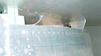
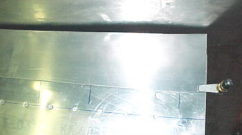
Lap joint showing outboard skin (right) slid underneath inboard (Left)
The skin is rolled away from the structure to allow access for the bucking bar. Some rivets are hard to see and a mirror is handy to check the formed head.
The riveting that we did was far superior to that done by Van's on the rest of the wing. Many of the factory rivets were driven with to much gun force and too light of a bucking bar or were insufficiently dimpled or countersunk. Kind of disappointing.
Right wing panel mostly done
11/12/01
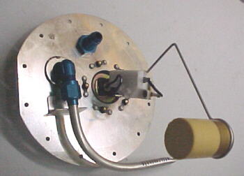
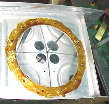
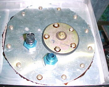
We got the riveting on both the outer wing panels done. I sealed the fuel sender covers onto the tanks using suitable compound. Don't forget the screw threads and heads.

The aileron gap seals were cut and notched then drilled and clecoed in place.
11/18/01
Before installing the fuel tanks, I decided to run the wiring in the wings for nav lights, pitot heat and the wing leveler servo. Wring was run inside 1/2 inch vinyl tubing for chafe resistance.
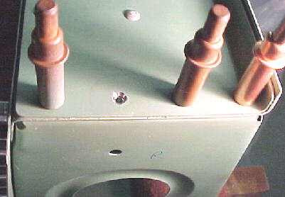
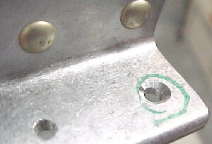
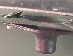
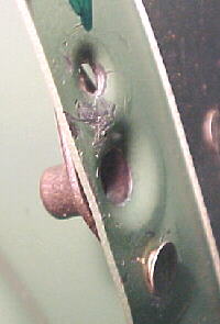
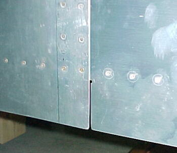
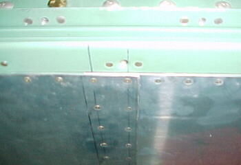
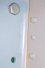
I put the tanks on next and wondered why some of the screws did not go down properly. I took the tanks off. What did I find? Another Van's screw up. #@$%*&#?? They forgot to dimple 21 of the trailing edge machine screw holes, 12 on one wing and 9 on the other. These cannot be dimpled after the wing is assembled so I had to countersink them by hand with a deburring bit as you can't pilot with the nutplate in place. I was not happy. The logical process of steps would be the drill all the holes, dimple ALL the holes and rivet the nutplates in sequence. Van's did not do this and the dimpling was randomly done. I'd advise anyone building an RV to check these before attempting to install the tanks. I also had to re-dimple the tank skins as the factory did a poor job and some were flattened out by installing the screws without a dimple underneath.
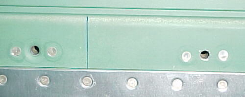
More of Van's "quality" work. Right hole is supposed to be dimpled for a #8 flat head machine screw just like the left hole was.
11/25/01
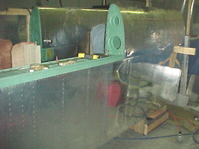
Finally started fitting the wings to the fuselage. The first thing that we found out was that there was no way that Van's assembled my wings to my center section. The bottom spar caps touched in the middle before the right bolt holes aligned. I removed the right wing and filed about .045 off the bottom spar caps. The wing then fit properly. The bolt holes have to be reamed for all the bolts to fit properly so be prepared to do this. Also drill or ream out the holes in the 4130 spar doublers as the zinc chromate in the holes will not allow the bolts to go through properly.
I fitted the ailerons to check for free movement. Both bound on the gap seals. By pulling up on the upper trailing edge skin, this was fixed. It appears that the left and right wing airfoil shape is not the same near the trailing edge exactly.
12/03/01
Still struggled with wing attach bolts. Spent over 7 hours reaming everything out so the bolts went in properly. Van's did a very poor job here with some holes out .030. Les Davenport reported similar problems fitting the wings on his 6A as well. I used SAE bolts to hold things together for fitting so as not to damage the AN bolts. I'll save these for final fitment at the hangar.
12/14/01
The next job was to measure for wing rake and incidence angle. I made up an aluminum sheet gauge to tape to the wing as per the manual for determining the incidence angle. After levelling the fuselage at the canopy rail mounts (0 degress on left side, .2 degrees on right side), I drew a line on the rear spar joints close to the fuselage.
Next, I determined that the wing had a slight forward sweep. This was done with a square against the firewall and a straight edge projecting from the fuel tank edge forward. Unfortunately Van's did not make the hole for the spar to penetrate the fuselage side high enough to get the wing square. The spar had to be trimmed and the fuselage hole enlarged considerably to correct this. Not easy to do with the wing on. By measuring at different stations along the wing, I found the left panel had .3 degrees of washout at the tip with the root set a 0. I don't know if this is intentional or not.
I clamped the rear spar to the tab and used a 6 inch, #30 drill to pilot the hole through the spar and fuselage attach tab, enlarged to .250 then .3125, also with 6 inch bits. Sweep forward in the wing can be corrected with a cargo strap hooked through the aileron pushrod hole and around the stab/fin attach points.
12/27/01
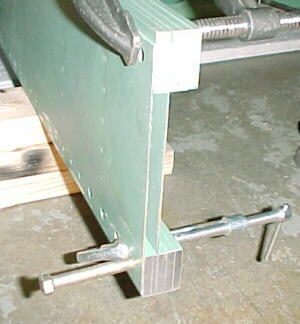
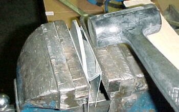
The front wing/tank attach fittings need to be bent slightly to conform to the fuselage mating angle. I did this by clamping the fitting in protected vise jams and used a dead blow hammer with a piece of 1/4 plywood for protection of the fitting.
The fitting was clamped to the tank tab then after careful measurement from the existing rivets, holes were drilled from inside the fuselage through the fittings. Measure at least 3 times before drilling! Pilot drill with a #30 then carefully enlarge with a 3/16 bit.
Finish the installation by drilling the hole through the front of the fitting and tab. The D bit specified in the plans did not allow the provided bolts to go through. I enlarged to 1/4 inch. The tank tab can be slotted after removing the tank or wing later.
01/06/02
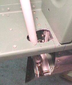
I trimmed the flaps to clear the fuselage. The left flap required a lot more to be removed, apparently because Van's did not build the fuselage sides even close to the same contour left and right. The left side was so far off than the flap actuator attachment bracket actually touched the side of the fuselage skin. Again, I was not impressed with the accuracy of the work performed by the factory. Next problem was locating the stock to build the actuator rods. The plans called for either an F659 or F659A. This did not exist but I did find an F-459A with the proper specs. The manual has no trace of PN F-459A in their listings??????? Drill this tubing with a #3 drill prior to tapping 1/4- 28 or you will screw something up. The plans don't mention this step.
I carefully enlarged the slot in the fuselage side/bottom for the rod to ensure full travel.The shape of the holes left to right was very different due to Van's earlier inaccuracies and the hole is not covered completely by the flap skin as designed. No surprise again.
01/29/02
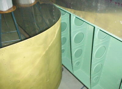
I started fitting the wing fillet fairings. Again,a lack of detail in the manual means you have to figure out everything for yourself. The bottom fuselage skins overlap the wing skins. Unfortunately Van's poor work here left me scratching my head again as the skins were not placed on the belly squarely. Would this have been so hard to do?
My upper fairings were not even close to fitting the fuselage contours and confirmed what I suspected above about the left and right fuselage contours being way off. Anyway, you need to carefully lay out a grid to be able to extend lines on the fairing to intersect the places underneath where the nut plates will go. Be aware of the flutes on the ribs where the nutplates cannot go. I had to leave quite a space near the spars as nutplates could not go in this area. The nutplates can be spaced about .250 from the edges on the tank flanges and .3125 from the edges of the wing skins. Don't get the upper aft nutplate too close to the flap LE. I left about .3125 from the fairing edge to the fuselage side for the rubber gap seal. You will have to trim this contour at lot. I wrapped tape around my marker to get this distance to draw the line on the fairing.
04/15/02
I had to trim about .250 inch off the entire wingtip flange to get this down to the .500 dimension that Van's manual said the flange should have been in the first place. This took a couple of hours using snips and an abrasive disc on a die grinder. I notched the tip for aileron clearance and installed the tip rib. I decided to make the tips removeable so I installed them with #6 screws on a 3 inch spacing. The tips were both too long in chord so they will have to be trimmed to line up with the aileron trailing edges.

06/30/02
Removing the wings now for the last time I hope. Added nutplate to front wing attach fittings. Rivets here should be -6 not -5 as stated on the drawings.
07/15/02
Cut, filed and radiused slots in the front wing mount fitting attached to the fuel tanks.
Drilled and dimpled wing roots for K1100-08 nutplates to attach root fairings. This takes a while.