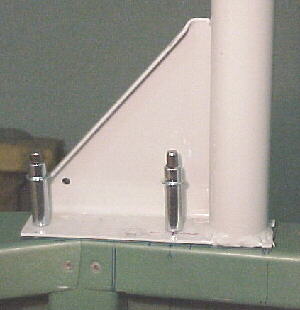
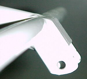
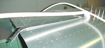
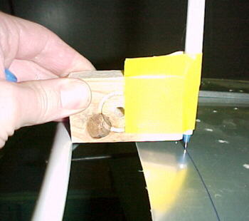
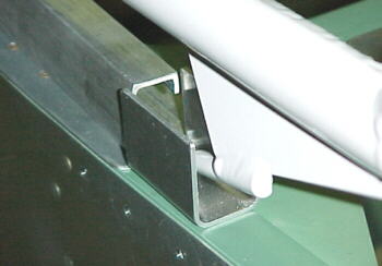
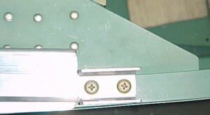
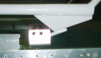
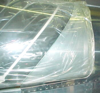
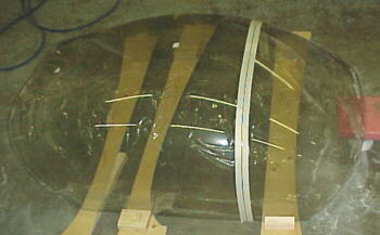
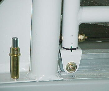
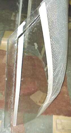
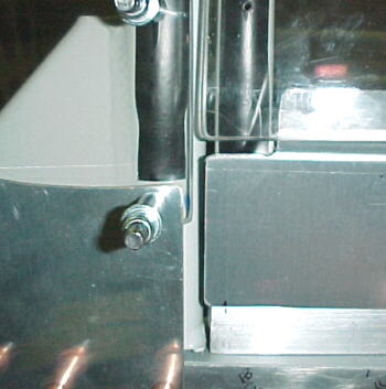
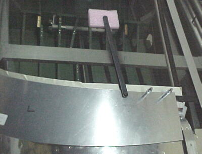
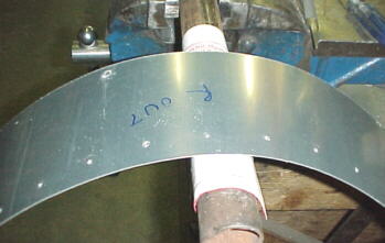
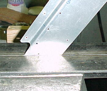
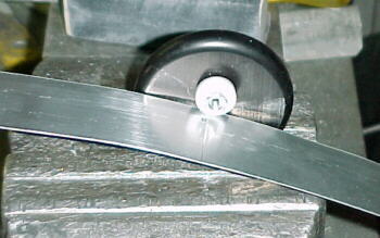
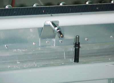
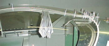
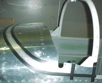
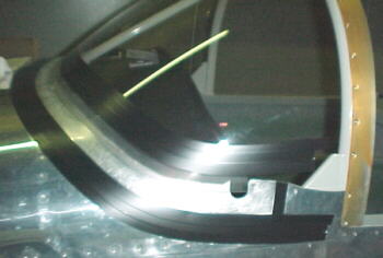
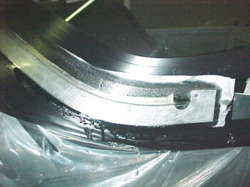
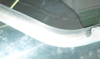
Notice flat base and angled sill junction


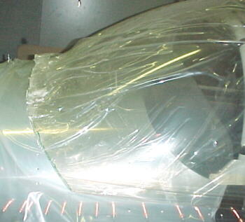
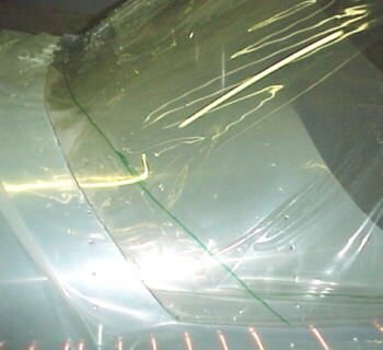
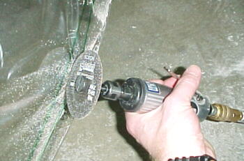
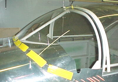
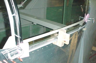
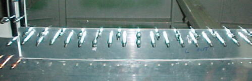
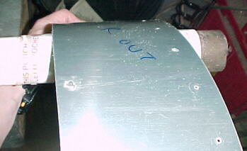
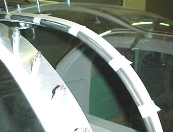
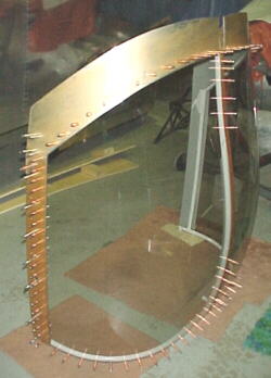
11/16/00 Windshield Frame
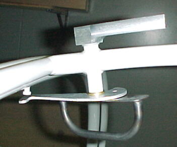
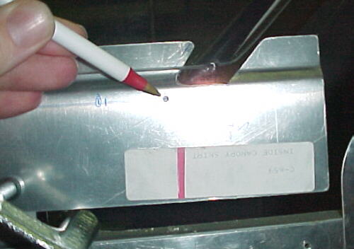
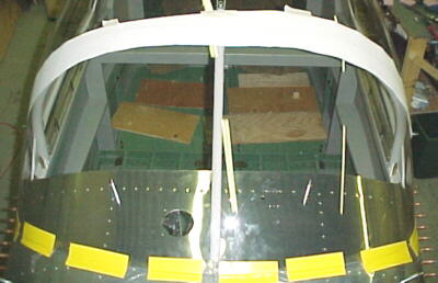
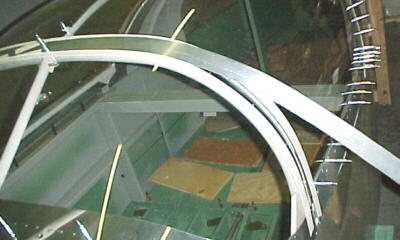
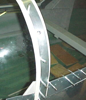
Back to more bitching about the manual and plans again I'm afraid. The W-641 windshield frame/roll bar is as with all of the welded assemblies from Van's, a beautifully made piece. I do question the design of this part and the method of attaching it to the airframe. For want of an additional 1/4 inch on the base plate length, the critical nature of the front bolt placement would be alleviated. A very slight error here and the nut will hit the upright fuselage section. Additionally, the flat plate bridges an unflat portion of the canopy sill which simply is poor practice on fastened assemblies. The C-668 spacers are also a hokey design. Some doublers should be attached to the upper angle longerons before the canopy sills are riveted on. Section D-D on plan SC-2 shows the lower sill edge as 1/4 inches wide when in fact it is almost 3/4 inches. This fact makes it virtually impossible to get the C-668 into position for drilling. Additionally, rivets on the canopy sill can interfere with the C-668 plates. Mention of this should be made on the plans or manual prior to selecting rivet spacing and location. The factory riveted the right sill in place and had a rivet right where the C-668 would be. Anyway, 3 hours of screwing around and lots of measuring and I had 4 pilot holes drilled.
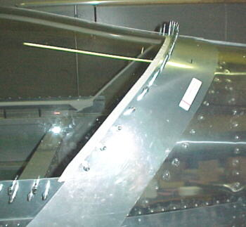
Notice flat base and angled sill junction
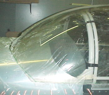
The manual has lots of photos of the tip up canopy installation and very few for the sliding canopy. This needs to be addressed.
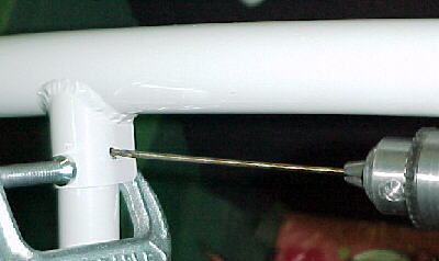
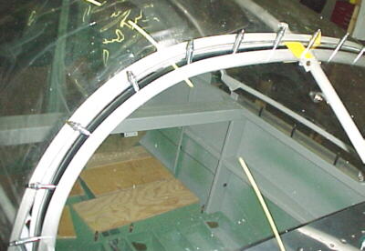
11/19/00
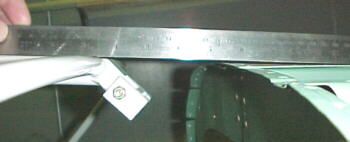
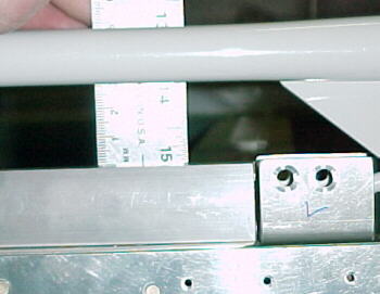
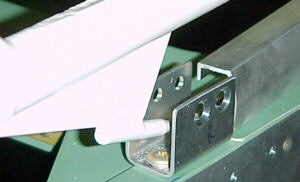
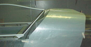
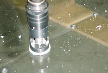
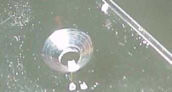
I marked the rivet spacing in the F6109 doubler and drilled through the center rib and roll bar brace. I noted that the shape of the flat .065 brace tab is vastly different from the plans and that the possible rivet spacing was also different. The manual wants you to drill a 1/4 hole in the upper roll bar capture and stainless brace. How you are supposed to get this straight is beyond me as the hole location is far less than the radius of any drill or chuck that I have even with a 90 degree drive. This part should have been designed differently or drilled at the factory. The best I could do was pilot drill with a 3/32 drill and flex a long bit to try to get the hole parallel to the main hoop. It turned out within about 5 degrees. DO NOT start with a 1/4 drill or you will make a complete mess of it. The drill will want to crawl and the stainless is tough and slippery as well.
I cut the slot in the front skin for the roll bar brace tab and trial fitted everything. I found that the welds interferred with the skin and had to be reshaped a bit.
05/26/01
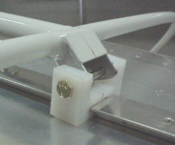
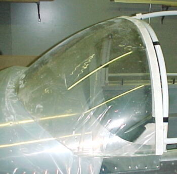
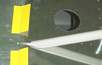
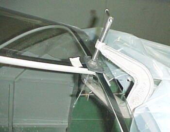
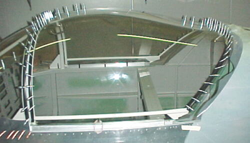
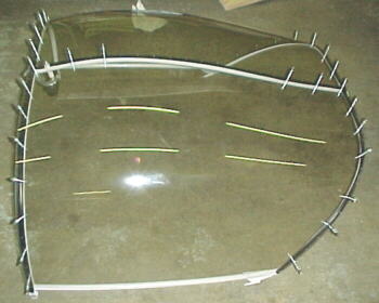
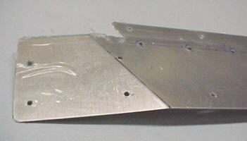
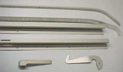
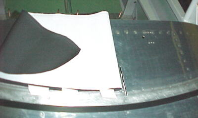
Several more frustrating parts on the canopy: The hardware to assemble the canopy rollers was contained in no less than 4 different bags. It took 45 minutes just to get these together by consulting the inventory list. Why wouldn't all the roller hardware be in one bag? Wouldn't that be logical? The manual really sucks with regards to the canopy detail. There are nowhere near enough photos for the sliding canopy. This is possibly the most exacting construction process on the whole aircraft yet there is the least amount of detail here. Why? I spent over 2 hours getting the latch shaft through the spigot in the canopy frame. The latch shaft was .002 over 1/2 inch and the spigot was .006 under 1/2 inch. Couldn't the factory have reamed the spigot so the latch shaft fitted? I pissed around with drills and flapper wheels way too long here.


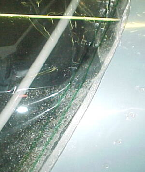
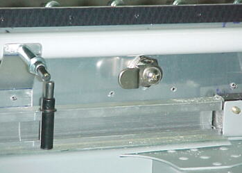
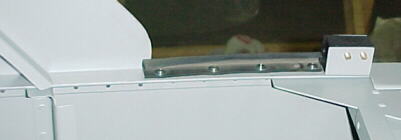
Sliding canopy latch and front roller detail
05/28/01
I started working on the rear slider rail. The plans had no information on rivet spacing to attach the two parts so I decided to drilland tap for 4-40 stainless, flathead screws instead. This allows the part to be disassembled and hard anodized later as well. Next problem was that the manual never stated that the C 661 slider block needs to pivot to follow the guide rail and if mounted as per the plans, it cannot do this. I put the canopy frame on my belt sander and radiused the front corner of the block mount so that it could pivot properly. I can find little reference in the manual about how the canopy sits in relation to the top of the fuselage deck other than it should be flush or slightly above. Doesn't this seem rather important? Mine fits slightly above but can be adjusted up or down a bit.
05/29/01
It was a little hard to determine the centerline of the upper fuselage due to the fact that Van's didn't get the contour of the fuselage sides the same. Depending on where you measure from, I could only get it within 1/16 of an inch. The plans say to cut the upper skin and fold down to clear the rear nylon slider block, unfortunately, their dimension is wrong. This needs to be about 2 inches wide to clear the 1.875 inch wide block, not the approx. 1.625 shown on the plans.
05/30/01
I trimmed the skin and cut the notch for the slider block. Then drilled the rail to the fuselage.
After looking through the parts index, C666 (rear skirts) are not actually numbered on drawing SC-1. Hard to find these in the big pile or figure out where they go. Hey Van's, ever heard of exploded views? They would really be of help here with so many overlapped parts. Actually, more than 2 photos of the sliding canopy would help. Come to think of it, actually showing all components on the drawing would be nice... Oh, to dream of a real set of drawings and manual for my RV...
05/31/01
The top track was bolted on and the skins roughly trimmed. The canopy now slides back and forth.
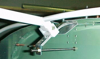
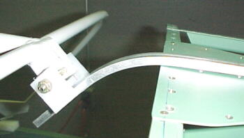
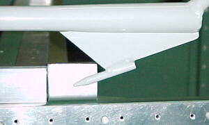
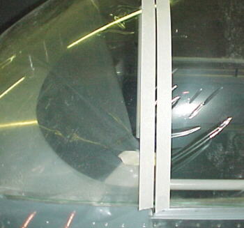
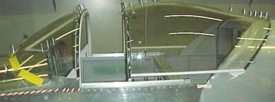
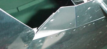
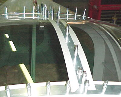
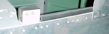
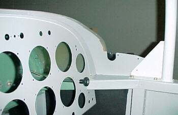
Note angle trimmed on rear block mount to allow swivel and adjustment stud through baggage bulkhead
06/06/01
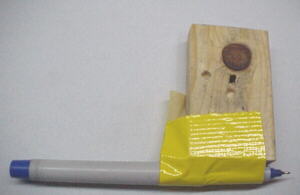
Looking for details on the C 624 nylon strips in the manual. No mention. Are they tapped for the -6 screws or what? Anyway work proceeds on the skin. I finally decided on trimming the skin 3 inches back from the canopy frame. I taped a marker onto a piece of wood and drew the line.
06/11/01
I had to tweak the canopy frame in about .250 inches to fit the fuselage properly. No matter what I did, the canopy frame just seemed a bit too wide for the fuselage, especially at the rear. Moving on the the seemingly simple lower rear capture blocks, C677/C665, the first thing to do was to get the canopy frame level at front windscreen frame and rear. The best determination on height made the lower horizontal frame parallel to the canopy rails. Mine measured at about 1.18 inches.
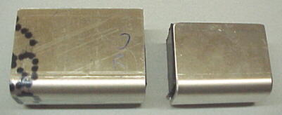
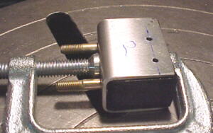
It was then determined that the block assembly was too tall and too long to fit. I trimmed mine down to 1.5 inches long and 1.125 inches in height. The HDP material cuts very slowly and files very slowly as well. A bandsaw and coarse, sharp, bastard file works best.
I marked the position of C677 and pilot drilled to #30. This was enlarged to #12. I found that the kit called for -10 screws to hold these to the longeron but only found -12 screws in the bag. These need a couple of washers so that they don't bottom the threads. Also, be very careful where you drill the front hole so it clears the angle part of the seat mount cross brace. Mine was ok at 5/16 back from the canopy rail back.
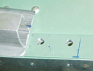
The cross bolt holes were pilot drilled in the drill press and countersunk.
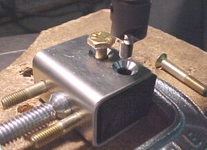
C677 was put in position to check the horizontal and vertical alignment of the canopy spike. I drew a line on the side of C677 corresponding to the angle of the spike, measured in to the middle of the spike entry and tried to estimate the angle to drill the hole in C665.
I determined the angles to be about 18 degrees and 4 degrees which agreed with the plans quite closely. These angles were set up in the drill press vise. I held my breath and started drilling.
I must have done a pretty good job. When I pushed the block onto the spike with the canopy just off the stops, the alignment was within 1 degree.

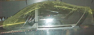
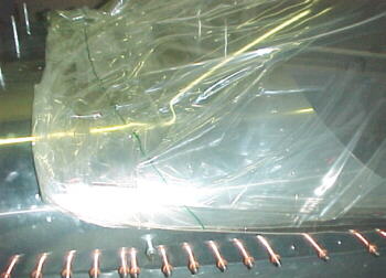
06/27/01
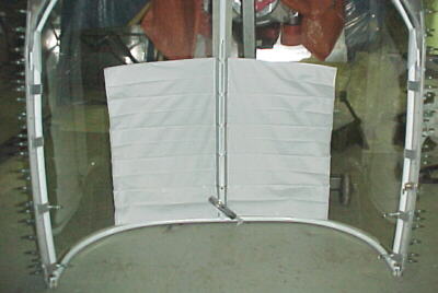
I taped some plastic sheeting up on top of of the front and rear fuselage skins to protect them from sliding the canopy back and forth. Foam strips were placed on top of the center frame tube to protect the canopy as well.
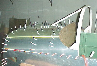
The canopy was then sat on the frame and moved back and forth to determine about the best position. It really did not conform to the tube very well no matter where it was placed. I took my best guess and marked where the initial trim cuts would be front and rear.
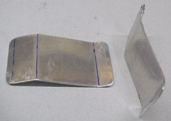
After first cuts
I then sat the canopy on the frame again and marked the 2nd cuts front and rear.
The cuts were made with the supplied cutoff wheel mounted in a die grinder.
These are the photos after the 2nd cuts:
07/16/01
I determined the high points of the canopy and frame by placing an electronic level on these two pieces and marking the contact point on both with masking tape. This helped a lot in determining the fore/aft placement of the canopy over the frame. I kept trimming small amounts off the front edge of the canopy in an attempt to lower the assembly closer to the roll bar/canopy frame. It became clear that the canopy did not really match the contours of these structures. I eventually could not trim any more off as the canopy was nearly up against the front roll bar fore/aft support tube.
Finally, after convincing myself that I had trimmed the thing enough. I carefully centered the canopy aand positioned it fore and aft as best as I could judge, I took a marker and put dots on the canopy where the two frames came together. I then carefully ran two strips of masking tape about 1/16 inch away from these dots, forming a gap about 1/8 wide to guide the cutting wheel through. Mark centerlines on the canopy or tape before you cut so that you can reposition the pieces again.
I took a deep breath and EEEEERRRRRRREEEEERRRR. Be sure to support the canopy with some wooden blocks as shown. As you cut the assembly, it loses strength and tries to spread apart. Three minutes later I had the canopy cut in two pieces. Looks alright so far. Probably the scariest operation on the whole aircraft to this point.
07/23/01
The next operation was to mark the hole to drill for the canopy latch shaft. After lining up various marks and drawing an X where the center of the latch hole was, I was ready. I tried drilling in a scrap piece of plexi first to make sure my intended procedure worked. I drilled a #40 hole first, enlarged with a 3/16 plexi drill and went out to 3/4 with a unibit. This worked well. I place the canopy up on the frame and dropped the hole over the latch spigot.
I was very disappointed to see that the canopy frame did not even closely match the canopy contour. About 3/4 of the way back, the plexi is over a 1/2 inch away from the frame! I'm not impressed! Anyway, now having the canopy sit against the frame at the front allows you to gauge the height of the windscreen vs. the canopy edge. The best compromise was to raise my frame about .060 on the roller shafts. I C-clamped the roller shafts to the frame spigots and drilled for the -3 bolts. It is not possible to do this step accurately until you have drilled the latch hole. I taped the windscreen in position to check the gap with the canopy at the frame.
07/25/01
I decided that it was time to cut the notch in the top, front skin for the windscreen to dog through. The plans and manual are vague here again. I marked carefully and drilled the 1 inch hole and cut the slots. I then marked the windscreen for cutting so it would go through the slot. I tried in in the slots. It seemed to fit ok. I then trimmed the forward edges of the windscreen, rounding them in a smooth arc. I'd be very careful here not to cut too much off, forward of the slot or you could have a big gap between the skin and the windscreen.
08/01/01
I spent several hours shaping and smoothing the edges of the windscreen with a coarse bastard file. I radiused the edges witha fine rat tail file, then sanded with fine emery paper and then 320 grit aluminum oxide paper. The windscreen was taped in place at the front. I ran a strip of black electrical tape along the roll bar to indicate the contact point with the plexiglass. As you press down on th plexi, you can see the contact line. I marked 4 inch spacing along this line and started drilling #40 holes and clecoing from the center out.
08/02/01
I clamped the canopy in place after careful alignment and marked the contact points and hole spacing. I used a string to find the center tube centerline because the tube was not even close to the plexi here.
08/04/01
Drilled #40 holes and clecoed. One tip on drilling, put the drill over your mark and hand turn chuck a couple of turns before powering up the drill on each hole. This prevents the bit from slipping across the plexi. Note the gap in the clecos along the top of the canopy. This is where the gap between the tube and canopy was too great. I plan to drill these holes when I can get the assembly on the ground to ensure that the drill is perpendicular to the canopy so that the holes end up in the center of the tube. This is too difficult leaning over the aircraft from one side. I plan to use rubber tubing to space the canopy off the frame and stainless 4-40 flat head machine screws in this area.
Once I had everything clecoed, I ran a marker around the rear tube inside the plexi to mark the final cut. I also ran a strip of masking tape about 1/16 above the top of the bottom horizontal canopy frame tubes to mark the position of that final cut.
08/09/01
I taped bubble wrap to the canopy for protection during the cutting, filing and sand processes. After cutting the trailing edge of the canopy to my mark with the abrasive wheel, I stood the canopy up on its front edge for trimming the sides.
I used the coarse bastard file to smooth the edges and then sanded with fine emery and then 320 paper. The worst is now done (I think). I mounted it back on the aircraft for safekeeping until the next step.
08/13/01
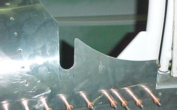
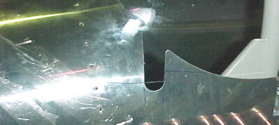
I cut the notches in the inner side skirts to clear the fore and aft canopy bow tubes.
I marked a centerline in the lower canopy tube. I marked a line on the skirt where the center of the tube intersected and drilled two #40 holes, one at each end. I had first established the height of the skirt to capture the plexi without interference in the lower capture groove. I lined up the holes with the centerline mark underneath and clamped the skirt in position.
I pre-marked the skirt with 1.5 inch spacing and drilled and clecoed the skirt to the tube. I then removed the inner skirt and clamped it to the outer skirt. Using the inner as a drill guide, I drilled and clecoed duplicate holes.
08/16/01
I decided to trim the side skirt so that there was a slight gap from the canopy sill rather than overlapping as Van's suggests. I didn't want the paint on the fuselage to get scarred up from opening the canopy. Drawing SC-2 has an error depicting section FF with an enlarged view which does not match with its location. I marked the second set of holes in the side skirt to penetrate the plexi. Be careful in locating these so that you have at least .250 from the edge of the plexi.
08/20/01
I worked on the rear skirts next. I trimmed the edges at the top, center to be parallel to the center canopy rail. I positioned the skirt edges about .063 away from the rail for clearance. The first upper hole through the rear canopy bow was carefully located on the skirt and drilled and clecoed. A hole finder is used to locate each subsequent hole in the skin. The skin must be kept tight as each hole is marked. Don't count on the skirt fitting tight at the top or the bottom. I haven't seen one that did yet until it is massaged a bit.
08/26/01
The top of the rear shirts are flat as with the fuselage shape and tend not to sit down tight against the fuselage. Also, there is a gap where the center canopy rail comes through the skirts which would be a big air and water leakage point. I fabbed a wedge shaped cover from .028 aluminum and a spring strip from .063 2024T3 to force the cover against the skirts and hold them close to the fuselage.
The side skirts still fit like hell on the lower, aft ends. I decided to take some of the outward pressure off structure by curving the straight skirts a bit. This proved easy to do with a piece of 1.75 inch steel tubing clamped in a vise with a cardboard roller taped over it. I just pulled the skirt over it, while applying pressure. This got the skirt about 3/16 of an inch closer to the fuselage skin.
I still had a 1/4 inch gap on the left side and over 3/8 on the right side. I took the plunge and decided to put a radical bend the the lower skirt and the inner support. I marked the bend lines, put the sheets in between two pieces of angle iron and put about a 10 degree bend in both pieces.
This worked very well and brought the skirts against the fuselage skins nicely.
Next, I worked on an overlapping trim strip, water/air piece. I decided that it should be posssible to make this from metal instead of fiberglass. I taped some paper over the windscreen/canopy junction and took a rubbing (dirty hands rubbing the paper and the windscreen junction). I transferred the outline of this template onto .032 3003 soft aluminum sheet and cut it out. Be sure to mark your centerline.
I positioned the strip carefully and drilled the center hole for a cleco. I re-checked and started drilling and clecoing outward using a hole finding tool. This was a time consuming job but way faster and nicer than a glass piece.
08/28/01
I rolled a slight draft on the leading edge of the strip to help it lay flat against the plexi and drilled a hole between each existing hole through the roll bar to prevent bulging.
I drilled and clecoed the rail fairing in place on the rear skirts and drilled the top cover strip to the center bow.
I fabbed 10 tabs to brace the lower edge of the side skirts for proper fuselage contour and to prevent the skirts from deflecting from vacuum and airloads. These will be riveted to the skirt and the lower horizontal canopy tubes. The second photo shows these in place along with the black plastic trim strips where the canopy mounting screws thread into.
09/02/01
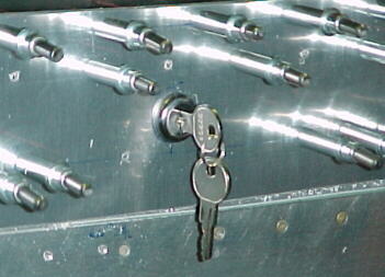
I needed some way to lock the canopy. After a bit of searching, I located a chrome plated lock set at Home Depot made by Prime Line, PN U-9941. This fit perfectly with no mods. After marking the location for the lock, making sure there was room for the mounting nut to clear the tube and that the arm was the correct height to engage the canopy rail, I drilled a .625 hole through the right canopy side skirt and enlarged with a rat tail file to the correct flat sided shape for the lock. I then latched the canopy and marked where the lock arm contacted the rail. I drilled some .150 holes in a line and joined them into a slot with various files. It took less than an hour and worked out well.
I didn't like Van's sealing solution on the canopy (none) so I went searching the auto junk yard for some suitable hollow weather stripping. For the windscreen/canopy seal, I found the trunk seal from a mid '80 VW Jetta could be trimmed to yield a 1/2 inch round section rubber which was light and highly crushable. I taped this in place to check the seal and it looks perfect. It will be siliconed in place after final assembly.
There was quite a large gap between the side skirts and the upper longerons, just behind the pin capture blocks. I trimmed a piece of offset, U sectioned weather strip from a mid '80s Toyota Celica taken from the aft hood/cowl junction. I drilled and tapped the upper longeron for four 4-40 stainless screws per side. This should fix most of the major air leaks. I plan to use soft, adhesive backed, weatherstripping on the rear fuselage skin to solve the minor gaps here.
09/03/01
I installed the Koger sunshade track and velcro tabs to the canopy tubes. This is a pretty slick device and well made.
09/16/01
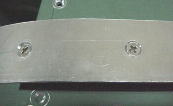
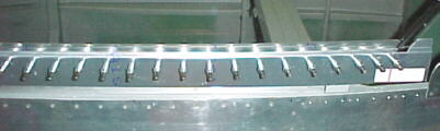
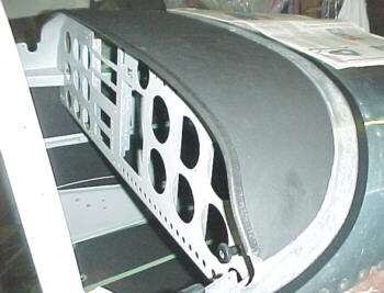
The finishing work is slowly being done on the canopy parts, drilling, countersinking, dimpling, alodining, painting etc. Some notes on drilling and countersinking on the actual plexi: The various rivets and screws used to fasten the plexi to the steel tubing structure have different head diameters. It is important to get the countesinks deep enough to get these fasteners flush and be sure that dimpled parts actually fit down flush properly and don't stree the plexi. I also found that the countersinks were too big to pilot into a 1/8 drilled hole so these had to be enlarged to #30. A standrad drill worked fine here. Be sure to carefully deburr the inside of each hole as well. I found the following upper hole diameter on the countersunk holes to work well for the specified fasteners: MK319BS rivets- .200, CS4 rivets- .240 inch, #30 dimple- .270, #6 screw dimple- .340.
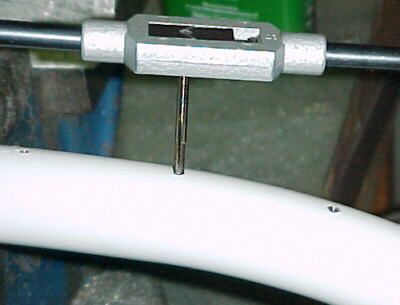
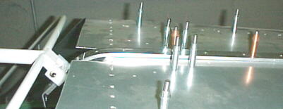
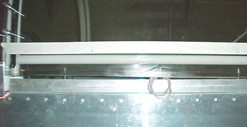
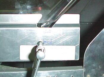
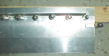
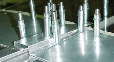
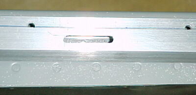
Tapping the roll bar for 6-32 screws, 2 inch spacing
09/28/01
I finally finished riveting the canopy all together. The aluminum parts were alodined first and the insides painted. It was very satisfying to get this done.
10/06/01
The canopy rails, rear slider parts, latch and handle were all hard anodized for easier operation, protection and to stop that nasty, black aluminum oxide stuff that you get with nylon rubbing on aluminum. Looks nice too.
10/14/01
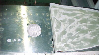
I had to paint the inside of the glareshield to match the rest of the interior. Had I thought of this before riveting the front skin on, it would have been easier. I masked off everything and sprayed it from the inside.
I sanded a strip 1.25 inches wide in front of the windscreen edge for the bonding strip using fine emery cloth. The line was marked and protected with electrical tape which is more flexible and tougher than masking tape.
Before starting on mounting the windscreen, I had to install the glareshield material. This was obtained from Cleavelend Tools and is a matt black, heavy vinyl material. The edge combing was also from Cleaveland. I traced a line on paper using the windscreen line on the skin. The paper template was cut .375 inside this line so as not to interfere with windscreen bonding. The template line was transferred to the vinyl and cut with scissors. I left about a 1/2 inch overhang on the edge to roll over under the lip for the combing to grab into without pushing the top vinyl back. The vinyl was laid in place and one half taped to the skin while the other half was carefully rolled back. Contact cement was applied to both surfaces. The vinyl side was left to dry for 20 minutes to seal the fabric, then had another coat applied. If you don't do this, the fabric will not stick well and you will have air bubbles which you can't get out.
The one half was carefully rolled down from the center out and smoothed and stretched slightly into place, then the other side was done. When dry, I did a little trimming with a zip knife, then installed the combing.
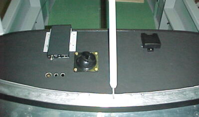
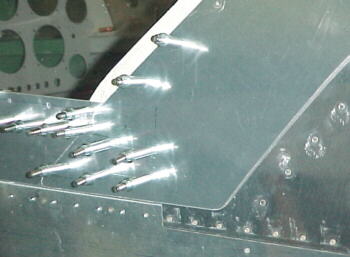
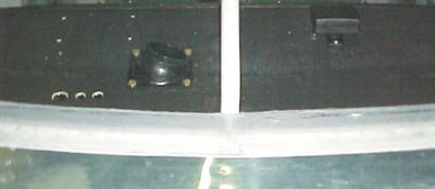
From left to right: Monroy traffic alert, defroster vent, roll bar brace, GPS antenna
10/15/01
The windscreen was protected with electrical tape one inch from the front edge. This area was sanded with fine emery cloth to roughen the surface for bonding of the attachment strip to. The area was then cleaned with Windex to remove the sanding residue. The windscreen was then attached to the roll bar and fuselage side with screws. Lexan spacers were fitted between the roll bar and windscreen to obtain the proper profile so that the canopy slid underneath the upper aluminum trim strip. The front skin and windscreen were then taped up for protection. Two 1.5 inch long strips of 5 minute epoxy were applied to the front base of the windscreen to hold it flat to the front skin. This permits a flex free junction to start laying the epoxy/fiberglass attachment strip to.
10/18/01
I ran a bead of 5 minute epoxy along the entire windscreen/skin junction to seal and bond the two parts. I cut out 2 strips of 2 oz cloth, slightly wider than the masked area, using a rotary cutter which works very well. I painted on epoxy resin and brushed the cloth down using more resin. With the shop at 65F, the 30 minute resin took over 8 hours to start to harden. First layer down, the rest should get easier right?
10/31/01
I laid 3 layers of 2 oz cloth down plus 4 coats of resin after those, sanding the last 2. Lots of final sanding to get a reasonably smooth surface. I not sure how those people building composite aircraft stay sane or interested doing this work. I'm glad that an RV is 95% metal! I'm also glad that the canopy work is 99% done at this point. It was a long haul.
04/17/02
For those interested in a combination tip up/slider canopy modification:www.aircraft extras.com