

08/05/02
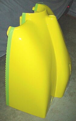
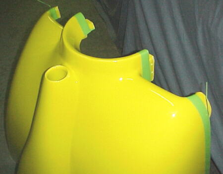
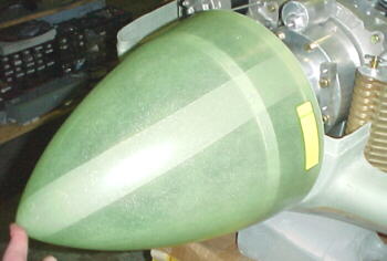
I used Van's 13 inch fiberglass spinner which is a beautifully made piece and a 13 inch back plate and 12 inch front plate also from Van's to fit the 3 blade IVO propeller. Van's service was super quick on delivery of these parts ordered online.
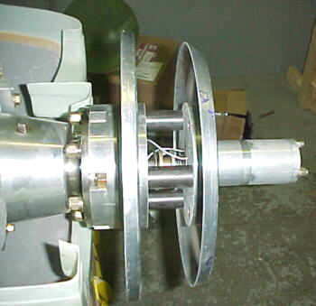
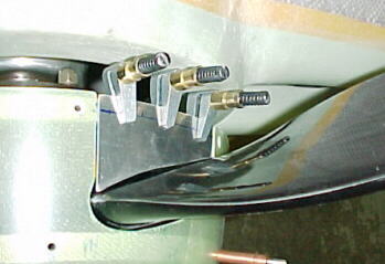
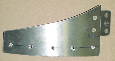
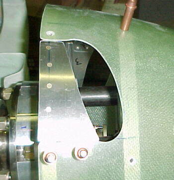
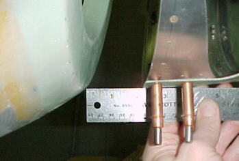
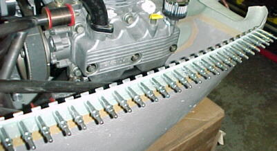
I machined 3 tubular spacers to simulate the thickness of the prop blades while jigging and fitting the spinner. Note that the urethane spacers supplied by IVO are about .050 thicker than the blade shanks and should not be used for jigging the spinner. My prop and redrive used the same SAE #2 bolt pattern as the Lycoming plates supplied by Van's however new, smaller 1/2 inch holes had to be drilled. This was easy as the flanges already had two 1/2 inch holes staggered between the larger holes and the plates used the same 2.25 inch hole as the IVO motor hub snout. I pushed a short piece of 2.25 inch tubing into the center holes to center and marked the other 4 holes using an 11 inch front plate at a template. The holes were pilot drilled and enlarged to 1/2 inch using a unibit.
Careful thought and layout regarding blade position and retaining screw location is called for. I installed six #8 screws on the front plate and 9 on the back plate. Mark the plate edges for screw location as these can be seen through the translucent spinner for drilling. A cardboard template was cut for the blade cutouts. This shape was transferred to the spinner.
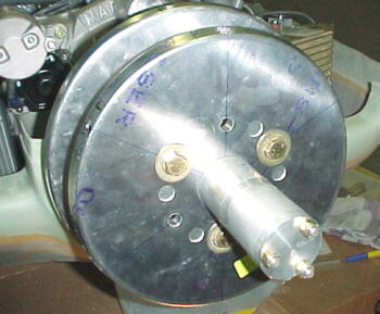
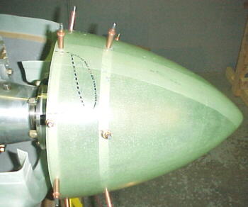
Plate nuts were installed on the spinner plates and the spinner countersunk for #8 flat head screws. Prop blades were installed to fit spinner with blade cut outs.
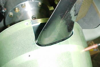
After marking the blade cutouts on the spinner, I used a 1.25 inch hole saw to start the rough cut. These were joined with a cutoff wheel. I cut way inside the marks initially!
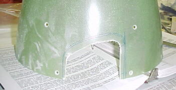
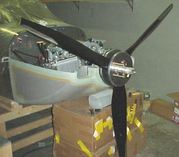
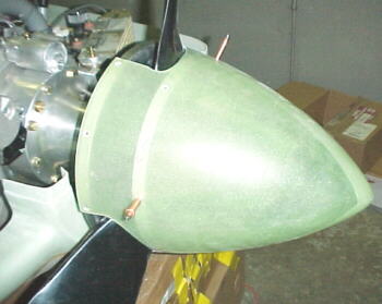
I used mostly sharp coarse bastard files to remove the rest of the material. These give better control and reduce the fine, evil dust produced by other cutting methods. Removal of material is fast using a 14 X 1.25 coarse file and touching up with 5/8 round and a 1 inch half round. Edges were finish sanded and the assemby installed. Looks like the front of a plane now!
08/07/02
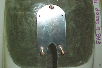
I fabbed some rear blade cutout covers from .040 6061T6. These were riveted to the rear spinner backplate.
08/09/02
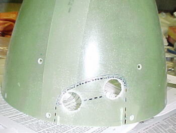
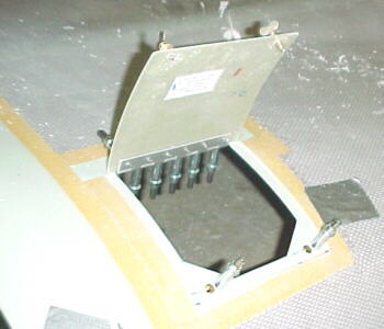
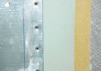
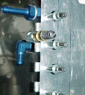
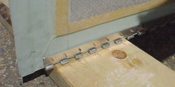
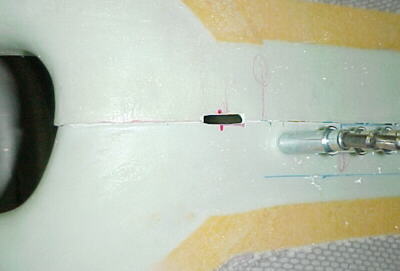
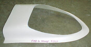
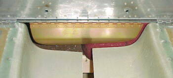
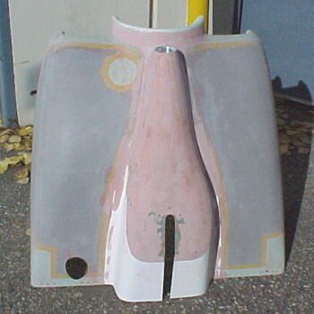
The oil filler door was trimmed out with a bandsaw and filed/sanded smooth to fit in the opening on the top cowling. The hole in the top cowling was started with some hole saw cuts, joined using a hacksaw blade and filed to outline with a coarse bastard file. I filed an additional .200 recess into the top cowling end for the hinge to sit (see photo). Drilled the hinge and cowling for -3 rivets. I placed a .032 spacer under the door side hinge only to space the hinge properly with the cowling side. Drilled the door and cowling for the camlocs. Do not drill both holes to .375 as the plans state. Only the cowling is drilled to .375. Drill the door holes .250 and file a small notch for the camloc pin to fit through.
08/12/02
The manual is pretty light on details for mounting the cowling. I had ordered the C/S cowling for the IO-360 figuring it would be the longest and used Van's 1/4 scale sideview drawing to mount my Subaru engine. Well, it turns out that my cowling is about 1.5 inches shorter than the one in the drawing so my prop flange is too far ahead. I have a 1.5 inch gap to fill between the spinner and cowling. Van's sells several different RV6 cowlings but I have no idea if they are different lengths.
After much screwing around, I drew a line 1 inch behind the fuselage front edge as a reference.I put the cowling in place as close as I could. Centered the cowling flange on the spinner backplate.
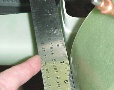
I measured from the line forward one inch and drew a line on the bottom cowling. I trimmed with tin snips to within about 1/32 of the line and finished up with a file for a straight edge. Re-fitted the cowling and found I had to change the angle just slightly. Drew a new angled line and trimmed with the file.
I cut the hinges and a .040 spacer strip for the side, cowling end hinges. I sanded a radius on the fuselage end hinges to clear the bend radaii on the firewall sheet metal. I then drilled and clecoed the fuselage side hinges in place. The bottom hinges were machine countersunk. These were clamped in place. Plans say to use .090 pins in a .125 piano hinge???? I jigged with 1/8 aluminum welding rod in place.
08/19/02
You have to trim away the flange on the lower cowling. I trimmed about .050 above the parting line with an abrasive disc and die grinder. I finished the edge straight with the coarse file. I also marked and punched the hole for my exhaust pipe.
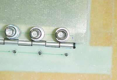
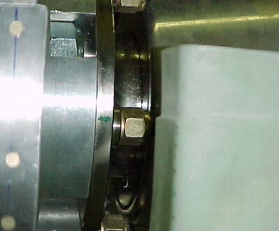
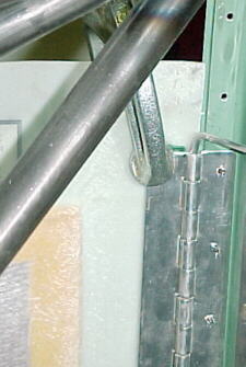
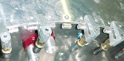
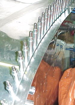
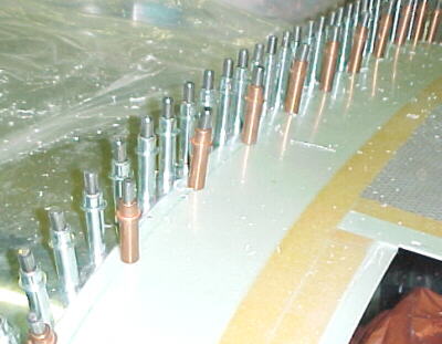
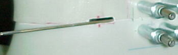
Photos below show hinge details
The top cowling takes lots of marking and removal to get right. Trim the major parts with tin snips and slowly remove material with the file. This will take several hours to get a good fit. It helped to cleco some tabs to the top fuselage flange for the cowling to sit on at the right height when the length got close. Unfortunately Van's had slipped with their die grinder and trimmed a bit too much off my cowling in one small spot. I'll have to add some material there. The front inlet areas took a lot of massaging with the heat gun and file to get ok although they will never fit the way I expect they should.
08/22/02
After wasting several hours screwing with the top rear cowling mounting hinges, I decided that this was a stupid idea. Trying to curve the hinges and insert the pins (Van's wants you to use .090 pins in the .125 hinges) was impossible through the oil filler door with my different engine components in the way. The smaller pins slopped in the hinges which didn't make me keen on this method either. After scanning many RV and Rocket photos, I see many used Camlocs on this area of the cowling with hinges on the straighter parts. This is what I plan to do.
08/23/02
I made a .020 thick spacer for the flange to get the cowling at the proper height. The flange had to be worked down and curved with a rolling tool.
08/26/02
I riveted the upper flange on and cut the NACA duct hole for the intercooler feed hose.
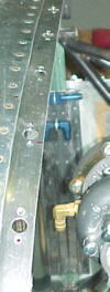
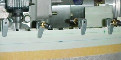
I cut the side cowling hinges and clamped them to the lower cowling. These are installed at a slight downward angle as per the plans. Drilled and clecoed to the lower cowling.
I cut a slot in the upper and lower halves to permit the hinge pin to be fitted. Starting at the front, I drilled and clecoed the hinge to the upper half.
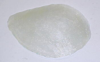
I taped off the starter area and applied clay over a plastic bag to make the fairing mold.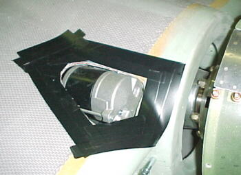
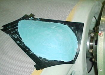
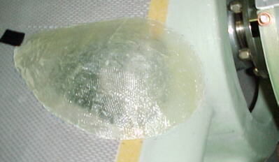
08/29/02
I applied 2 layers of 3oz tape over the mold. Pulled it off, washed it and used 5 min. epoxy to bond in place. Applied another layer of tape around edges to bond it to the cowling and build it up. Will use filler to shape and sand smooth.
09/06/02
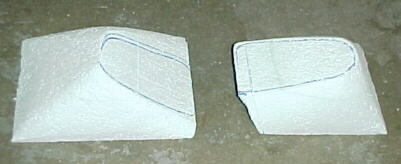
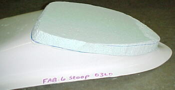
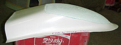
I moved on to the radiators ducts next. Aluminum frames were constructed to box the fin area in and provide a mounting surface for the composite ducts. I used the lost foam method to form the fiberglass. Foam blocks were shaped with a hacksaw blade, wood rasp and coarse sandpaper. They conform to the rad frames on the aft end and the cowling air inlet forward.
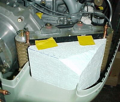
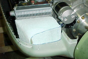
The cores were covered in electrical tape to smooth the major pits and coated with Carnuba wax to aid is peeling them apart.
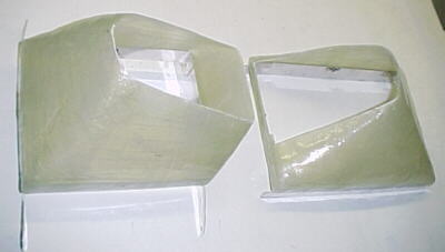
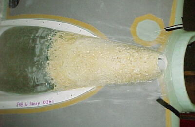
I modified the Van's O-360 lower carb scoop to act solely as the air exit scoop but slicing off the inlet hole. I glued in foam to reshape to a more streamlined shape. I was not impressed by the accuracy of this part. Everything was quite crooked.
09/09/02
The foam was shaped with a rasp and sandpaper. 2 Layers of 3oz cloth were put over top and one layer underneath when the foam is dissolved to bond to the original part.
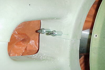
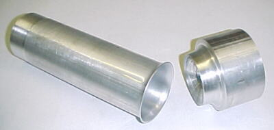
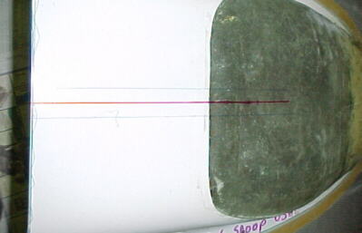
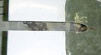
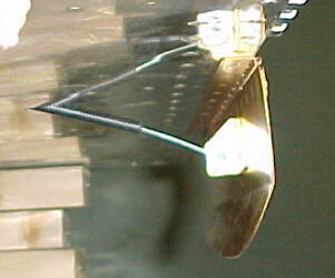
I machined a die to form a velocity stack shape into some 2.5 inch 6061T6 tubing for the turbocharger air inlet. The tubing was also machines to accept 2.5 inch SCAT hose on the other end to connect to the air filter. The end of the tubing was annealed to permit forming. The die and tubing was greased and placed in a hydraulic press to form the shape.
I cut a hole in the lower cowling for the tube to pass through. Initially, it is installed with 5 minute epoxy. It will be bonded into position with epoxy and cloth.
09/12/02
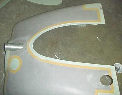
I cut out the lower cowling panel to leave about a .75 inch around to glass the scoop to. I drilled and clecoed for 1/8 countersunk head pop rivets and riveted the 2 pieces together using backup washers on the inside to prvent cracking and pullthrough. I layed out the cloth strips for each segment and longer pieces to cover for the second layer. I glassed the 2 pieces together. The trailing edge of the scoop needed about 1 inch trimmed from it to line upwith th rear cowling edge.
09/13/02
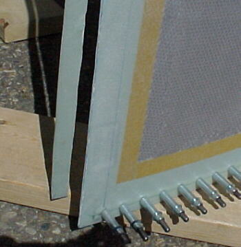
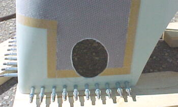
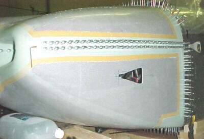
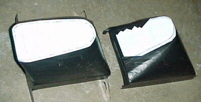
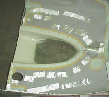
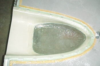
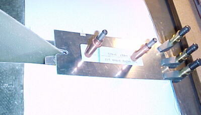
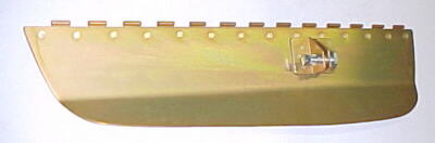
I trimmed the rad plenums, fitted plate nuts to the rad frames to mount the plenums to and checked fit in the cowling inlets.
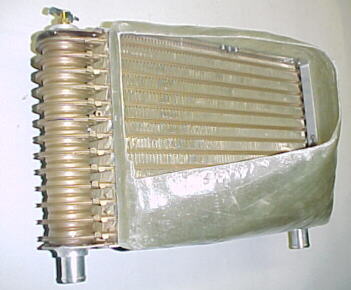

Left rad/ plenum ***************************Right rad/ plenum
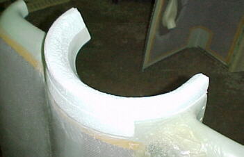
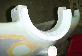
09/16/02
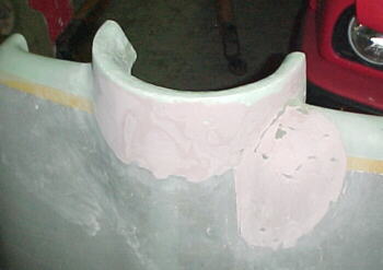
Foam rings were cut out and epoxied to the cowling to take of the space between the spinner. These were then glassed over.
09/20/02
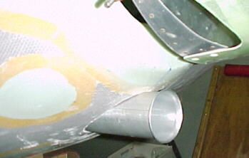
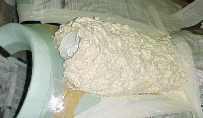
Urethane foam was used to build up and fair in the turbocharger air inlet to the cowling air exit scoop. This was rasped and sanded to shape and covered with 2 layers of cloth.
09/23/02
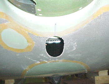
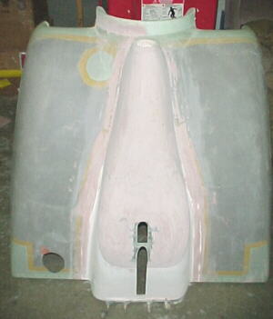
The lower cowling needs to have a slot cut in for the landing gear leg. I marked this 1.25 inches wide and started with a hole saw and cut the rest with snips and finished with a file and sandpaper.
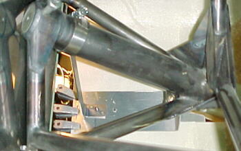
I did not like Van's complicated method of holding the rear of the exit scoop up plus with my cowl flap addition, one of the brackets would interfere. I custom fabbed a steel bracket that clamped to the leg mount and used most of the sandwich plates from Van's for the rest. Drilling the landing gear mount for the bracket bolts is fun. I did mine from above with a long #40 bit, removed the pieces and enlarged to 3/16.
09/30/02
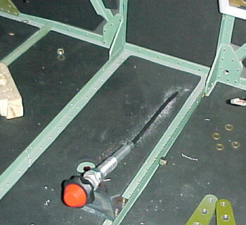
I made an adjustable cowl flap from .040 6061 T6 aluminum in hopes that this will increase cruise speed by a few knots. This was hinged to the bottom of the fuselage and activated by a vernier control knob on the floor. A gap was left around the flap for air to exit when closed to help reduce turbulence.
I used a flat aluminum plate to cover the gap ahead of the leg fairing rather than a fiberglass fillet. I applied body filler over the cowling modifications to smooth out the contours. About 10 more hours of sanding and the aircraft will be shipped out for painting after 37 months of work. A big milestone!
10/10/02
Finally done filling and sanding!
11/08/02
Cowling painted!