
Nov. 10/24
One of the leading tech questions that we get here, regards questions with mounting the Hall sensor and magnets on our E and F systems, so here are some more ideas on this topic.
Many people seem to have problems understanding the diagrams in the manuals regarding Hall sensor placement and magnet mounting. The diagrams are intended to be viewed as if they are transparent and that you can "look through" the components such as crank pulleys. Magnets and sensors can be mounted on either the front or back face of the pulley. Rear face mounting is more popular as this generally puts the mount closer to the timing cover. The fact that the Hall sensor is flipped 180 degrees is unimportant.
Magnets and Hall sensors do not need to be mounted at TDC. The procedure in the manual is clear if it is followed step by step. This is VERY important. We recommend that the Hall sensor location be chosen first to avoid any interference problems with fan belts, alternators, water pumps etc. The Hall sensor may be located anywhere around the crank pulley that is convenient. Once the Hall sensor is mounted, turn the crank to TDC #1. Put a mark on the pulley where the middle of the Hall sensor intersects the pulley. From this mark, go 80 degrees in the direction of crank rotation and make another mark. This is where the first trigger magnet is placed. The other trigger magnet(s) are placed either 180 degrees from this one on 4 cylinder engines, 120 degrees on 6 cylinder engines or 90 degrees on 8 cylinder engines. Trigger magnets are mounted with the blue end facing the Hall sensor. On F systems(coil pack), the synch mag is placed 40 degrees past the first trigger mag, in the direction of crank rotation. Sync magnet, the blue end of the magnet must face away from the hall sensor, so in other words the blue end should face down into the hole in the pulley.
It is very important that the Hall sensor mount be extremely rigid. Vibration and deflection of this mount may cause triggering and running problems. A good rule of thumb is, if you can deflect the mount by pushing hard on it with your hand, it is not rigid enough.
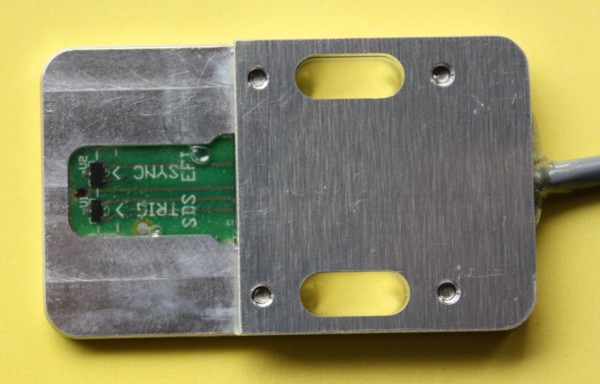
New F type Hall sensor, for coil pack systems.
This article includes step by step photos of the correct way to install the magnets and Hall sensor for a 4F system. This may help potential users.
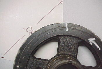
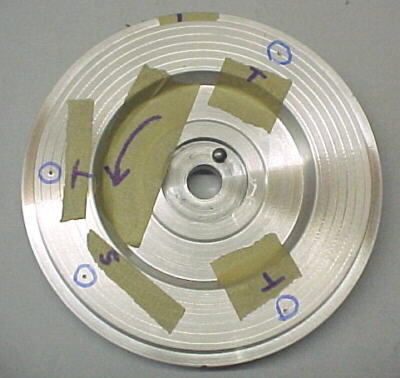
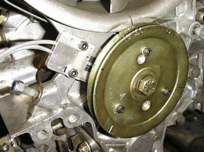
Step 1- Position crank pulley at TDC #1. Draw arrow on pulley for direction of engine rotation.
Step 2- Position Hall sensor for best location around pulley to clear belts etc. and for mounting bolt proximity. Mark the pulley where center of sensor crosses. This is the mark that you will measure magnets placement from, not from the TDC mark.
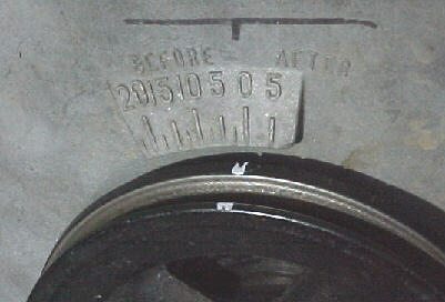
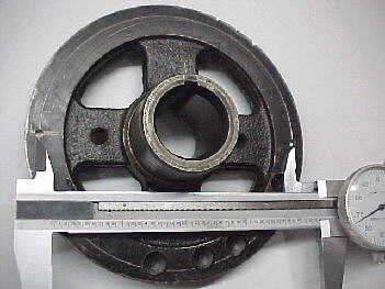
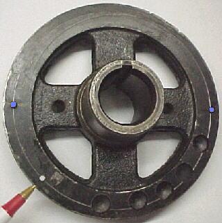
Step 3- Scribe circle as per manual and measure with calipers using the appropriate formula for 2, 3 or 4 magnets.
Step 4- Place 80 degree protractor against original mark from step 2 and other edge in direction of rotation arrow from step 1. Mark pulley here for 1st trigger magnet on circle.
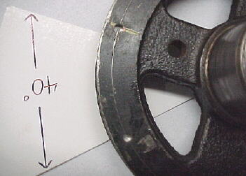
Step 5- Place 40 degree protractor "F"(coil pack) systems only against the 1st trigger mark from step 4 and direction of rotation arrow from step 1. Mark pulley here for synch magnet on circle.
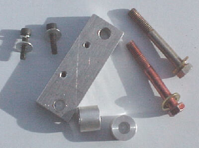
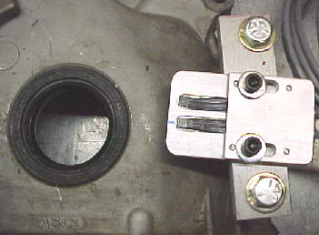
Step 7- Make up Hall sensor mount from 1/2 inch T6 plate, 3/4 bar stock spacers to span two timing cover bolts. Spacers should allow 1.5 to 2.5mm clearance from magnets to Hall sensor plate face.
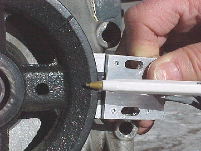
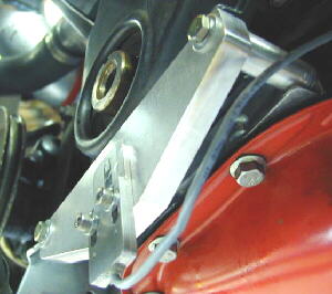
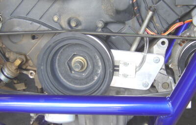
Step 8- Hall bracket in position
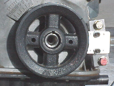
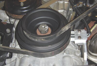
Step 9- Pulley and Hall in position
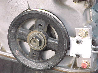
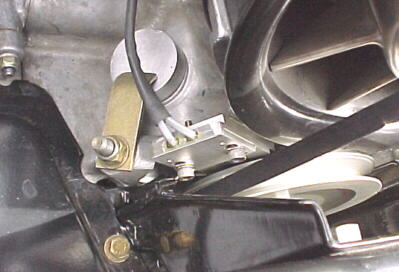
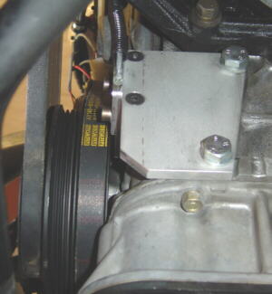
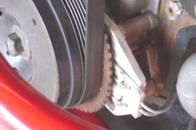
Step 10- Closeup of Hall installation

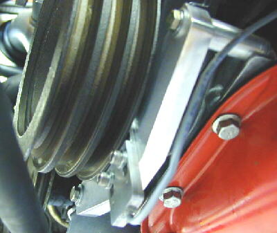
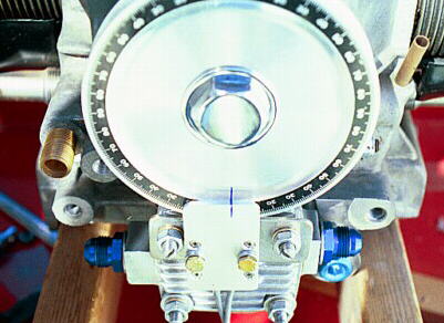
Step 11- Front view of complete installation on Toyota 2TC
It is important to note that the Hall sensor location determines magnet mounting position around the pulley. Before glueing magnets into position, use the following procedure to check that you have done things correctly:
1. Turn the crank to TDC #1
2. Now, turn the crank backwards 180 degrees, until the crank is at BDC, coming up to fire on #1 cylinder
3. Turn the crank in its normal direction, slowly by hand until about 120 degrees before TDC. At this point, the synch magnet on F systems should be crossing the synch element on the Hall sensor.
4. Keep turning the crank in its normal direction until it is about 80 degrees before TDC. At this point, the first (#1) trigger mag should be crossing the trigger Hall element
5. When the first trigger mag crosses the trigger Hall element, it tells the ECU to do the calculations based on RPM and manifold pressure and fire the spark at some amount before TDC which is now coming up. The ECU needs some time to be able to do the calculations and still fire the spark 20-40 degrees
before TDC. This is the reason for mounting the magnets so that they cross their sensors 80 degrees before the pistons reach TDC.
More tips:
The magnets should protrude equally from the pulley face around .040-.060 inch (1mm to 1.5mm).
Solid pulleys may have a magnet to sensor distance of as little as .040 inch (1mm). Rubber damped pulleys should have a minimum magnet to sensor distance of .080 inch (2mm). Magnet to sensor distance should never exceed .160 inch (4mm).
Always check magnet to sensor clearance by turning the crank slowly by hand before attempting to start the engine.
Make sure the coil power is disconnected when checking magnets. Magnets should remain SEEN for 3-4 degrees of crank rotation. If they are only seen for 1-2 degrees, they may be missed at higher rpm and the engine will stop revving at that rpm.
The sensor mount MUST be extremely rigid or you will have problems mising the magnet passage at certain rpms where the sensor vibrates. Take your time to build a proper, rigid mount along the lines of those shown in this article.
Installation on 4AG Toyota

Installation on Volvo 740 Turbo
Installation on an air cooled VW
Magnet positioning for 6F system installed on Porsche 911 pulley.
Hall sensor mark at top, A trigger magnet 80 degrees to the left, synch magnet 40 degrees past A trigger magnet, B trigger magnet 120 degrees past A trigger magnet, C trigger magnet 120 degrees from B trigger magnet. Note arrow to denote direction of rotation.
Above: F Hall sensors installed on two Porsche 911s.
The photos below shown some good mounts built by TCR Auto Performance in Tucson, AZ. Photos courtesy of Tim at TCR.
Acura 3.5L V6
Nissan SR20DET
Nissan SR20DET
Buick 3.8L supercharged V6
This link covers Hall/ magnet installation on a BMW 325i EM-4 6F system
Be sure to carefully follow the installation process described in the manual. This article is intended as supplemental help to the manual, not as a replacement.
Hall Sensor Alignment
Hall sensor to magnet alignment is critical. If your engine idles fine but encounters a severe miss at a certain rpm every time, there is a good chance that the Hall sensor and magnets are not aligned well enough. Even if they register SEEN when the crank is turned by hand, they may be on the fringe and might be missed at higher rpm. You can check Gauge 1 mode, watching rpm as you rev the engine up to the miss point. If the rpm reading suddenly halves or changes radically at that point, alignment is the problem. If the sensor is properly aligned, you should be able to turn the crank at least 3 degrees before the window changes to NOT SEEN. If you only can turn the crank 1 degree before it goes NOT SEEN, you are on the fringe and need to reposition the sensor.