

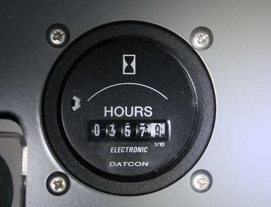
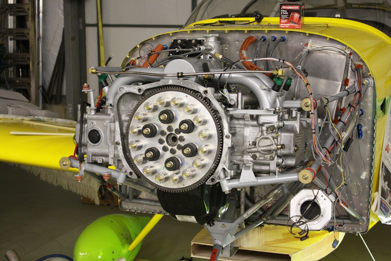
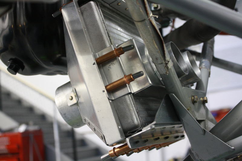
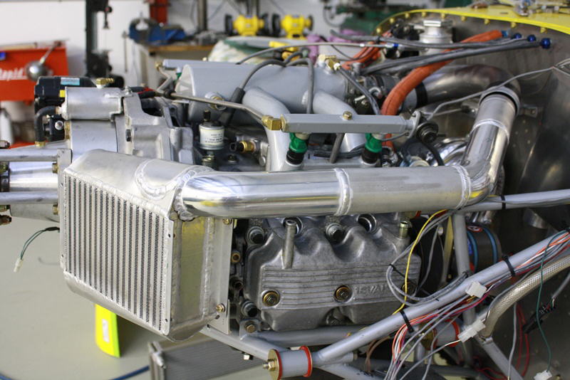
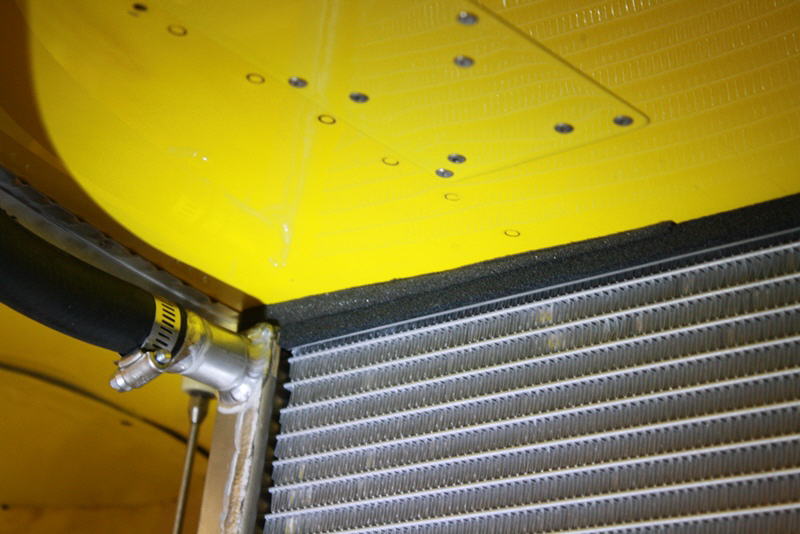
This page details the lessons learned, problems, solutions and new mods after 9 years and 357.9 hours on our Subaru powered RV6A. The engine is coming out for overhaul after oil consumption rose to a quart every 6 hours and compression had fallen to below 120 lbs. This is the first time the engine has been out of the plane and the gearbox removed from the engine.
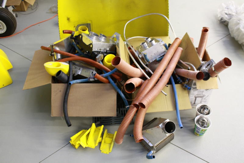
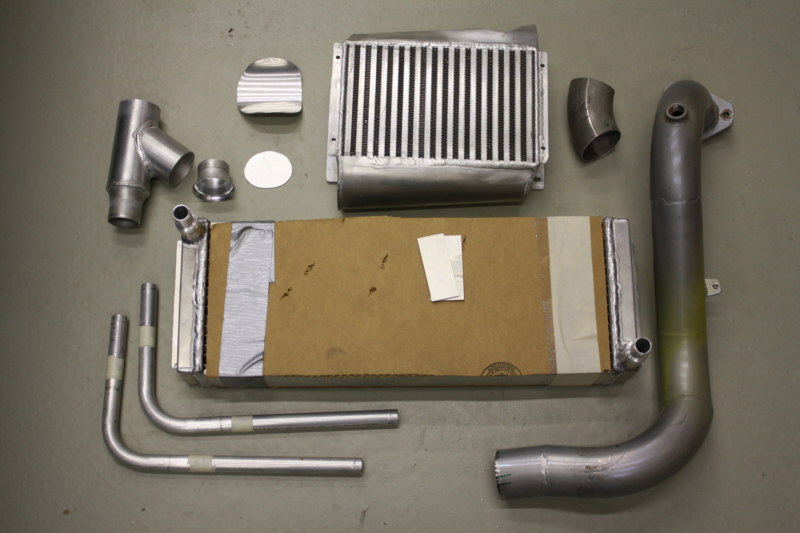
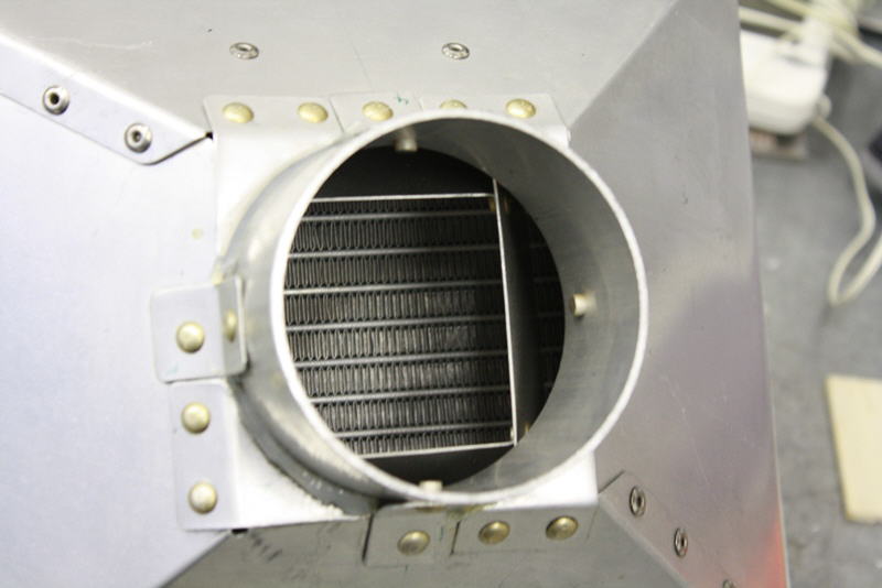
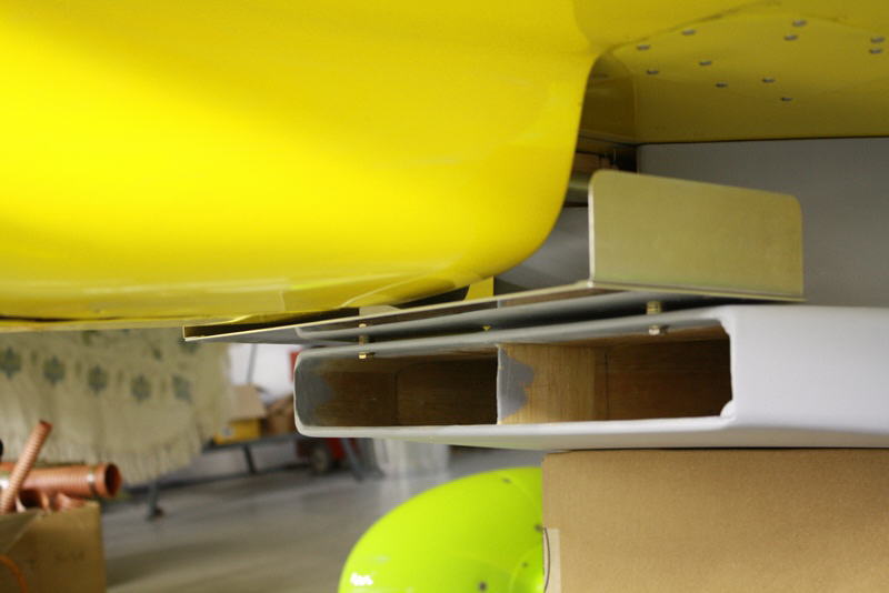
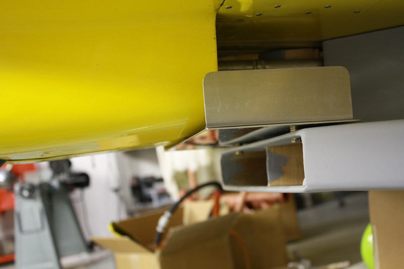
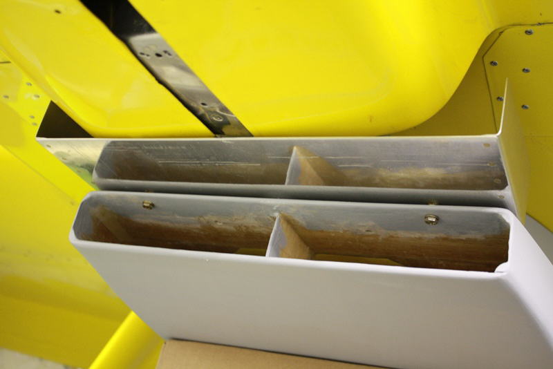
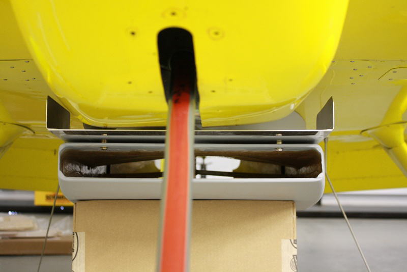
This is the 3 boxes and 55 lbs. of heat exchangers, SCAT hose, clamps, scoops and ducts removed from the airplane which will not be going back in. We'll be fitting a proper ventral radiator with scoop and adjustable exit door this time around.
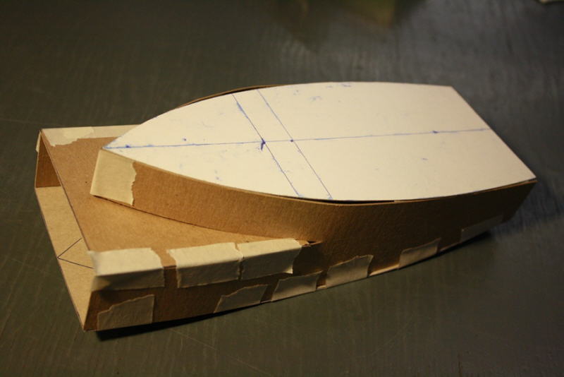
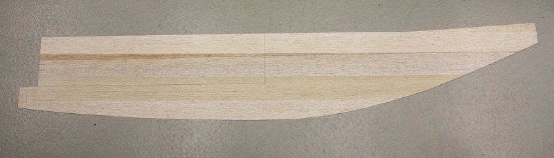
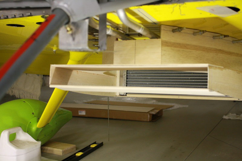
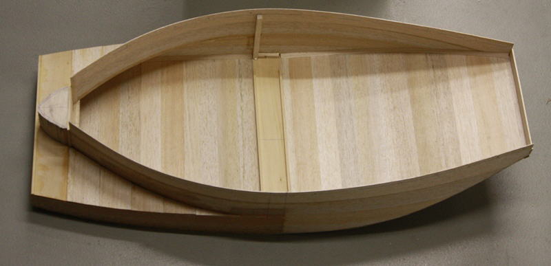
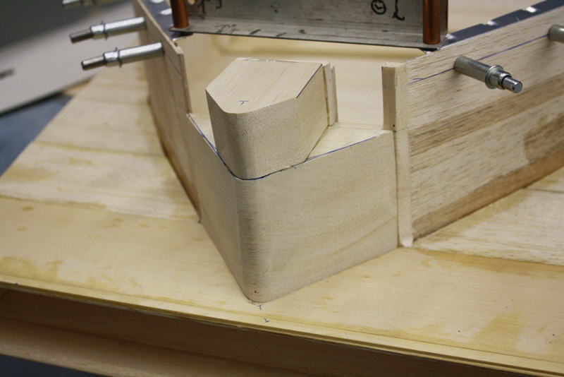
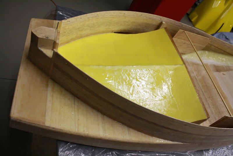
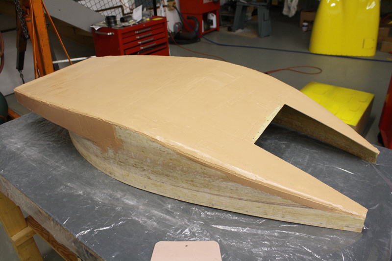
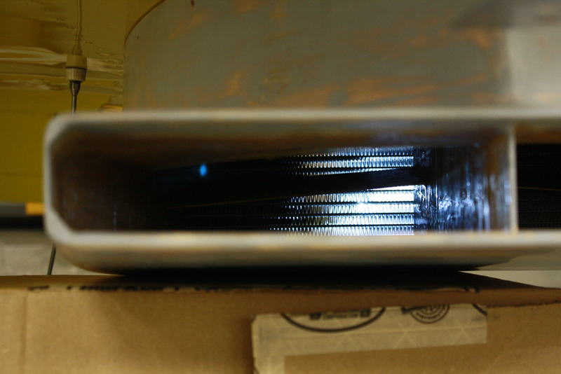
This is a carboard model of the approximate scoop shape to house the ventral rad. It will be constructed of a Balsa/ fiberglass expoxy composite.
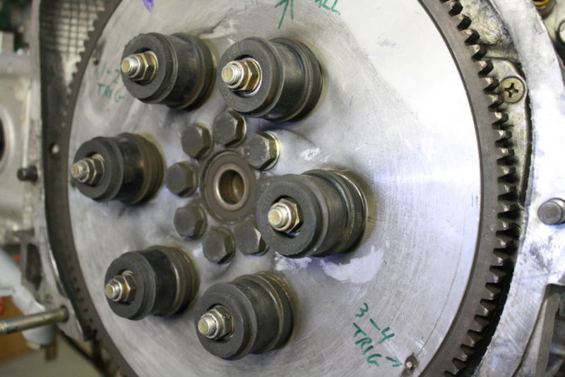
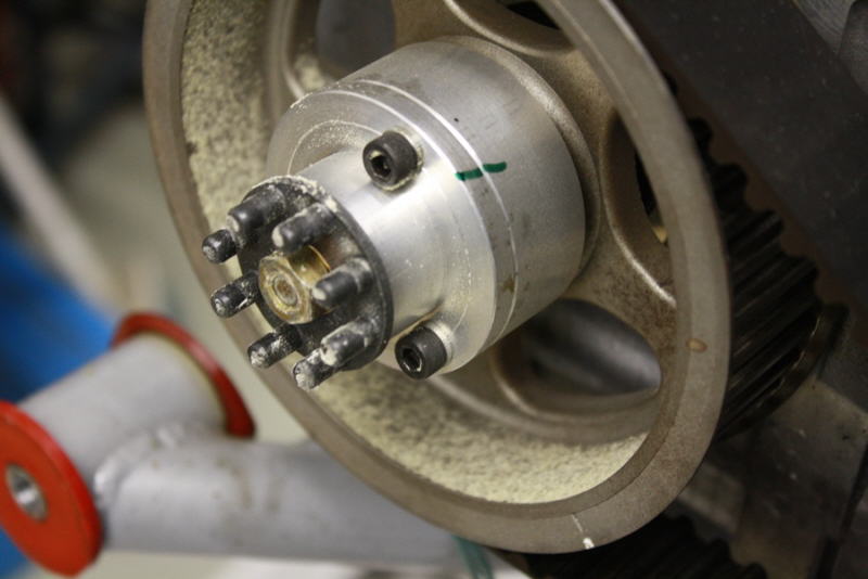
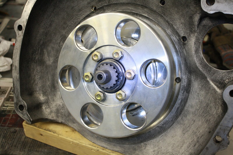
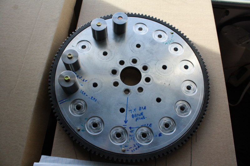
This is the Marcotte flywheel with drive lugs and rubber isolation bushings
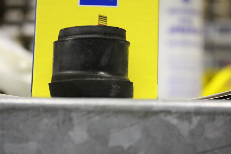
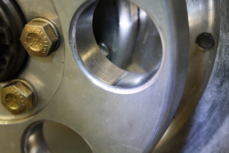
Closeup of bushing distress and permanent deformation due to the torque impulses
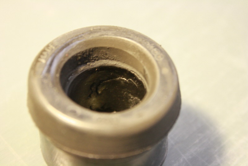
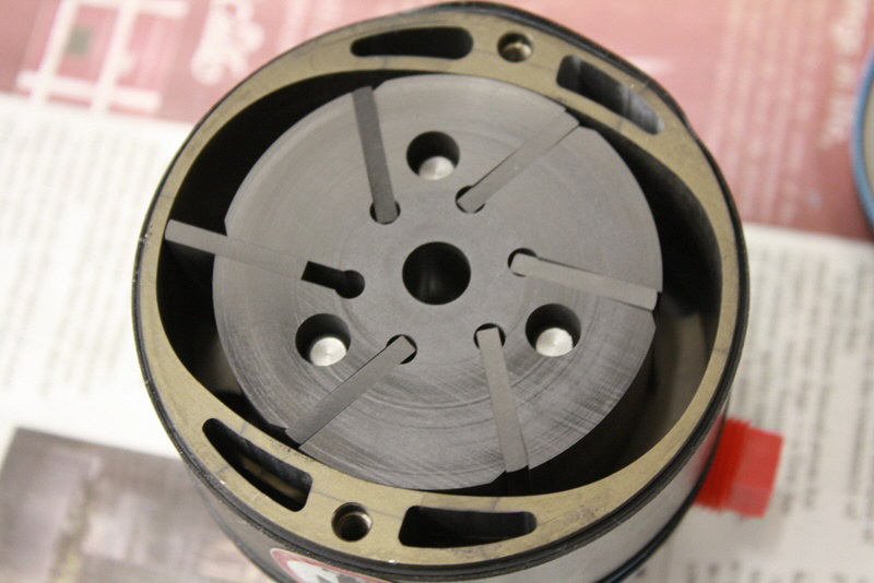
More internal distress after maybe 125 million cycles
Vacuum pump shear coupling showed heavy wear
Vacuum pump drive off left camshaft
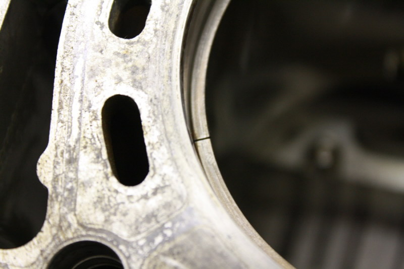
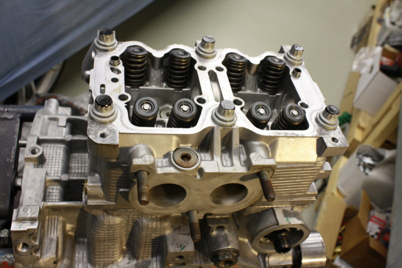
After removing the heads, there was no wear on the bores and the ring gaps were the same as when the engine was assembled. Mobil 1 works!
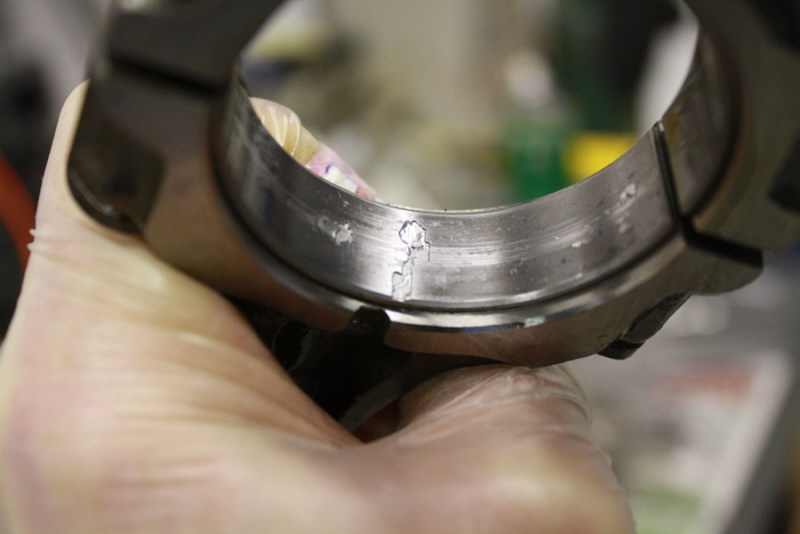
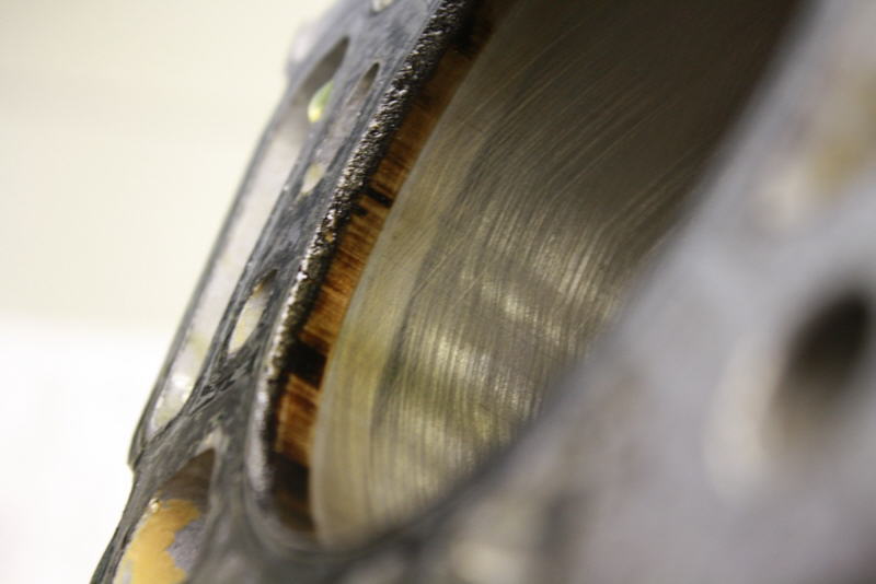
One surprise was finding cavitation damage on 2 of the upper rod bearing shells. I have never seen this in 35 years of building engines professionally. These were the original OEM aluminum faced, 2 layer bearings. I have switched to a harder tri metal ACL aftermarket rod bearing now.
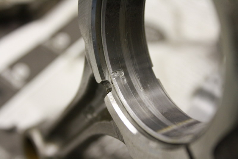
Other rod bearing with damage
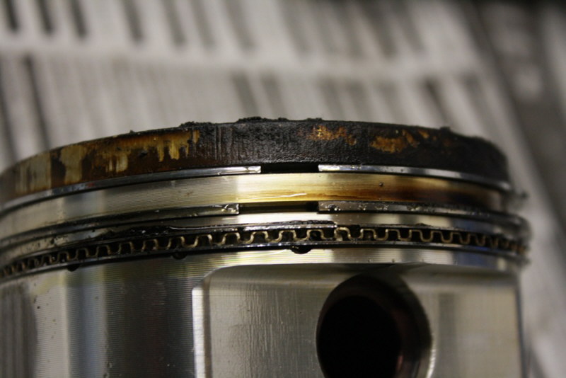
Shows the heavy carbon deposits from the high oil consumption. The upper rings had lost some static tension. There was one serious overheating event over 250 hours ago but oil consumption remained essentially unchanged for several years after that so it is not quite clear what was causing the high oil consumption. Everything else looked remarkably good inside as far as this was concerned.
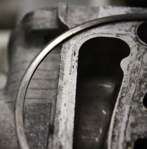
Ring end gap still same as 9 years ago
Loaded side of top ring showed .001 wear on bottom face
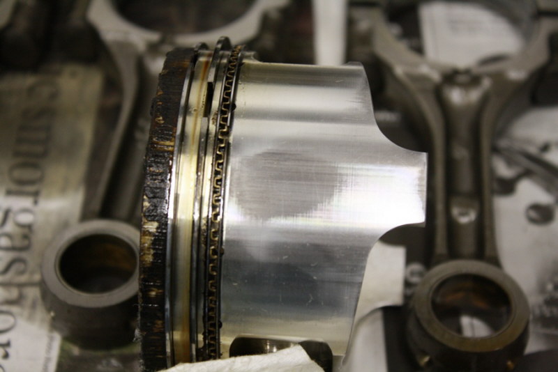
Skirt wear due to non-offset piston pins on the JE forged pistons. This was the worst one and still under .001
Back of the Marcotte M300 gearbox
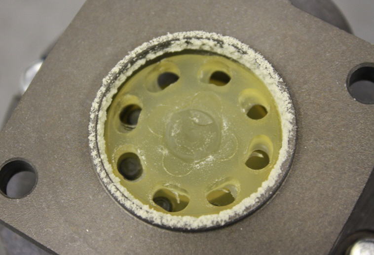
Strange wear where isolation rubber bushings contact gearbox drive ring.
Checked wear on the dry vacuum pump vanes
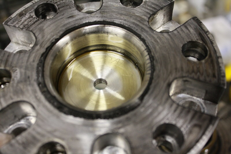
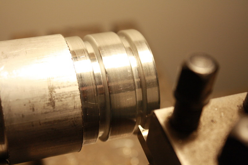
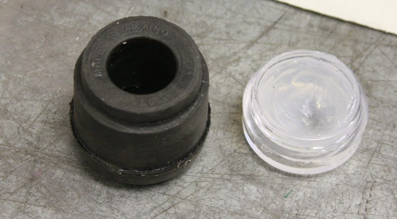
Unexpectendly found oil inside the prop hub. It appeared to be slowly seeping past the splines and locking nut. Will be fitting an O-ringed plug to prevent oil from exiting the hub.
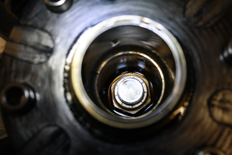
Oil inside prop shaft
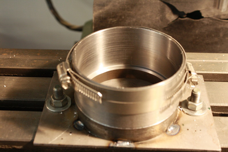
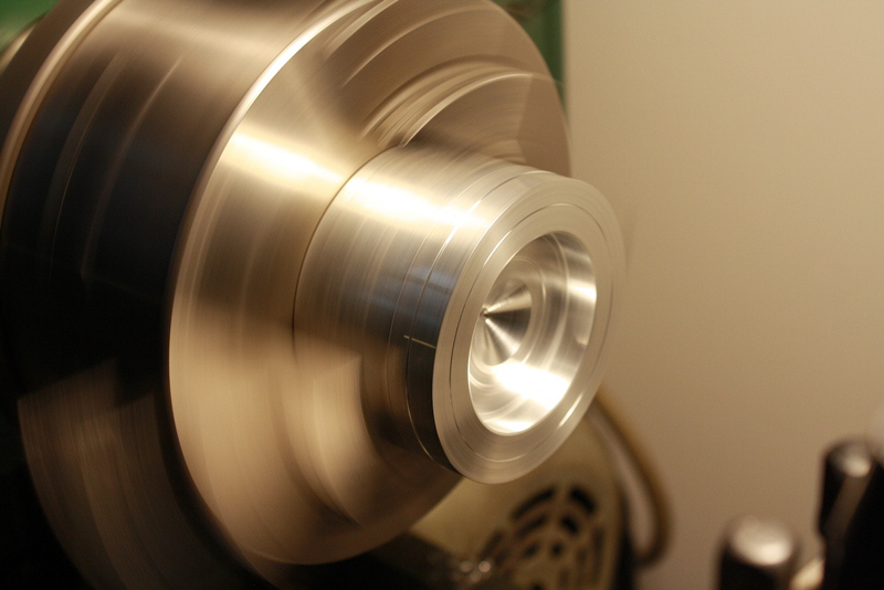
I machined a fixture to hold the pistons for machining
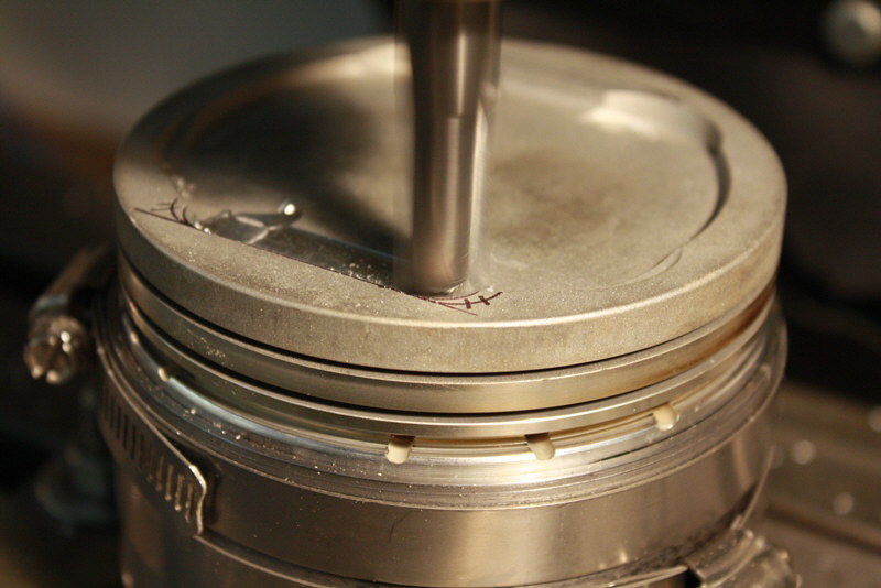
Milling a bigger dish in the pistons. This reduces the CR from 9.45 to 9.25. I want to run 91 octane unleaded fuel now instead of 100LL like the first 300 hours. There were pretty heavy lead deposits on the piston crowns, chambers and valves despite running Decalin lead scavenger since day 1.
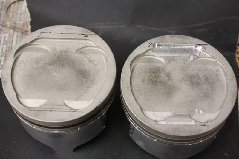
Pistons before and after
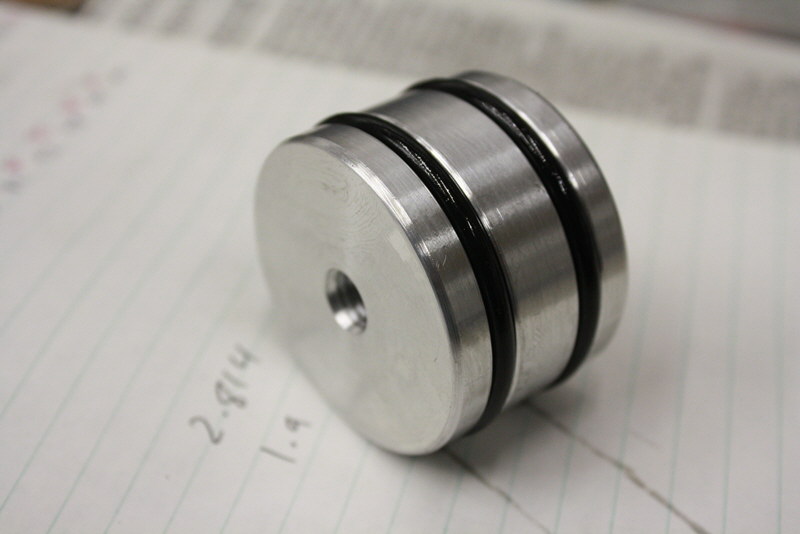
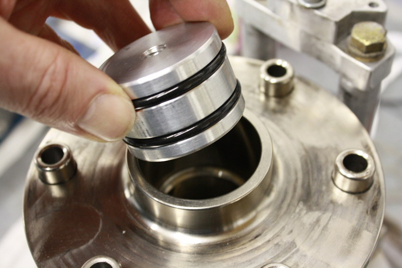
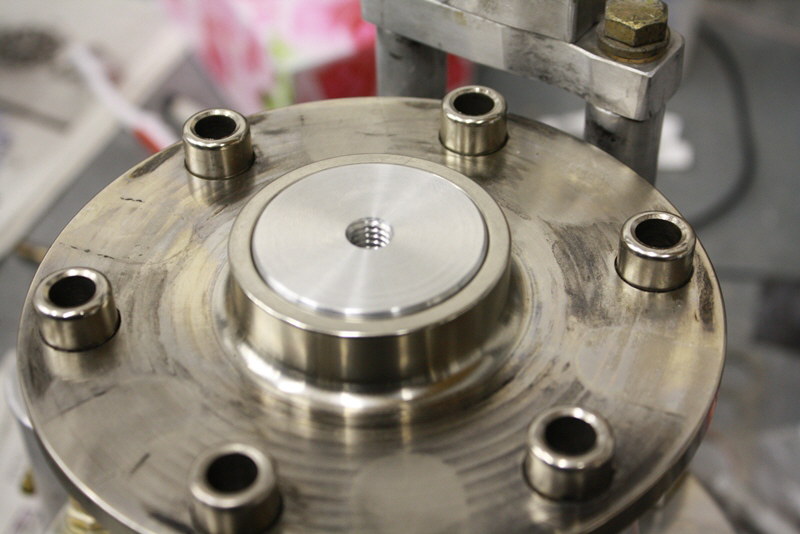
Machining gearbox nose plug
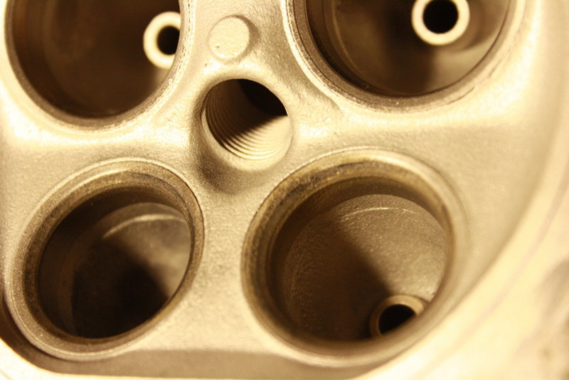
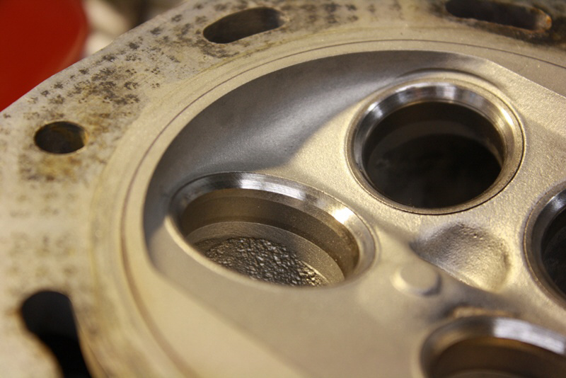
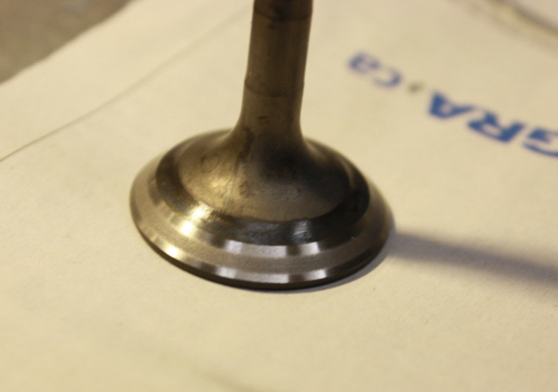
The exhaust seats were in rough shape
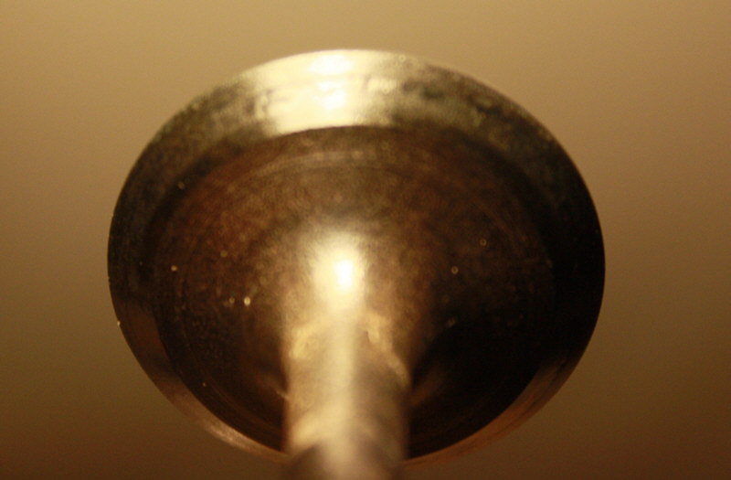
Ditto exhaust valves. Believe Subarus don't like leaded fuel in the long term. Others have reported similar valve issues when running 100LL. Most people have good results running mostly unleaded fuel. The exhaust valves were all leaking badly but none were burned. One intake valve was also leaking a lot. The seat material on these engines is not particularly hard. In this application, there would probably be a benefit to have harder seats fitted.
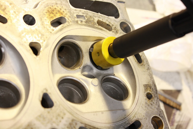
Re-cutting seats with carbide tools
Old and new surface
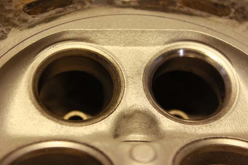
After 45, 30 and 60 degree cuts, before hand lapping
Jan. 23/13
Exhaust valve after hand lapping

Intake
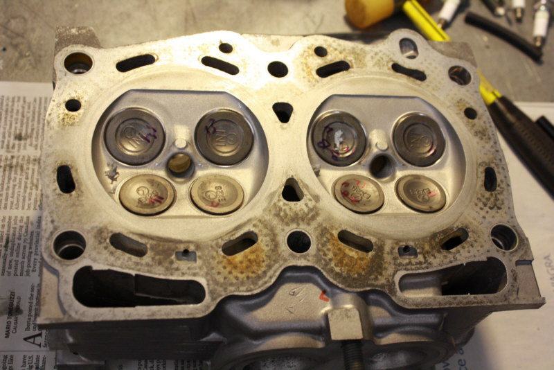
Valves installed in heads after lapping
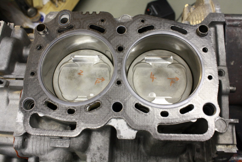
Pistons installed in block
Heads installed on block
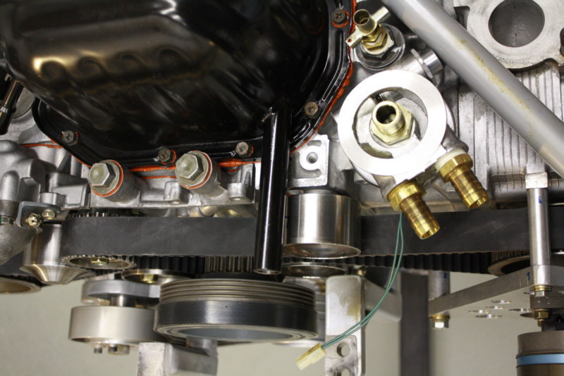
New positioning of turbo oil drain in pan will hopefully allow gravity flow and eliminate the electric scavenge pump fitted before. Originally when the plane was built, gravity feed was attempted but I believe windage and oil shedding from the crank near the drain outlet in the pan made this not work well. Have about 5 inches of head from the turbo bearing housing to the drain fitting, 3/4 hose size now.
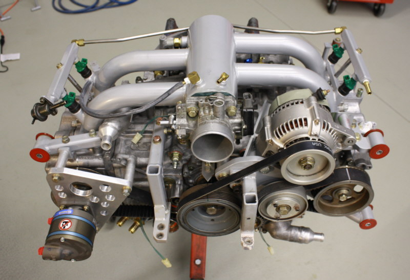
Engine assembled, ready to go back in
02/08/13
Machining adapter to mount PLX wideband AFR gauge
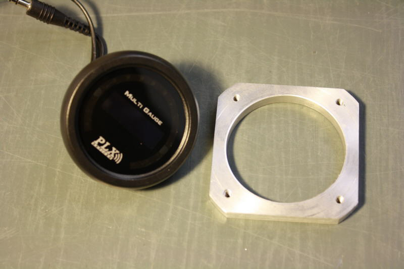
Finished adapter and gauge
02/11/13
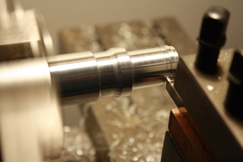
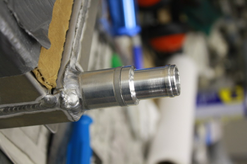
Machining new rad barb fitting for radiator
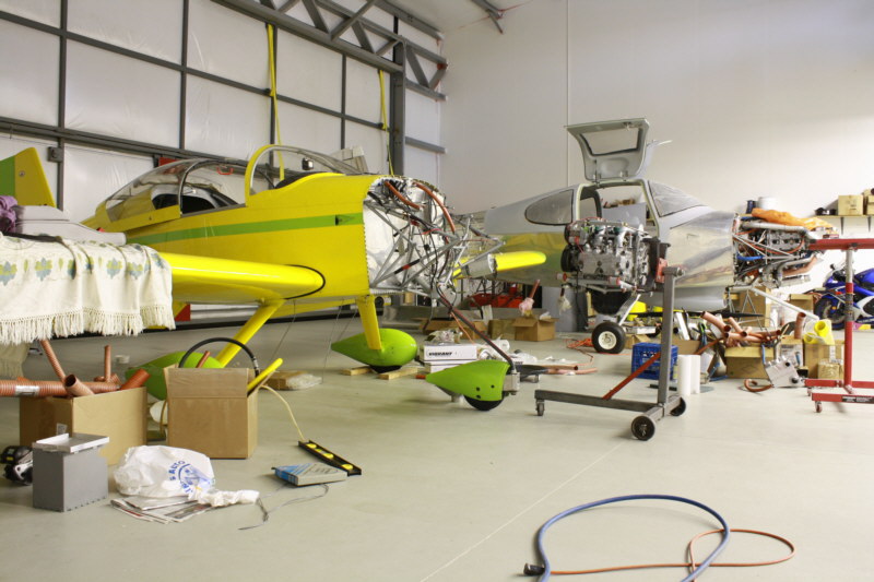
RV6A and RV10. Work in progress
Work on the coolant pipes, intercooler and turbine outlet pipe mods plus cabin ventilation mods. Fabbing and welding.
Just back from the CNC shop. Showing mods to increase flywheel inertia via 16 steel weights bolted through the aluminum flywheel. This will add about 8 lbs. to the original 7 lb. flywheel. Inertia tests to follow soon.
Coolant pipe assembly for belly radiator
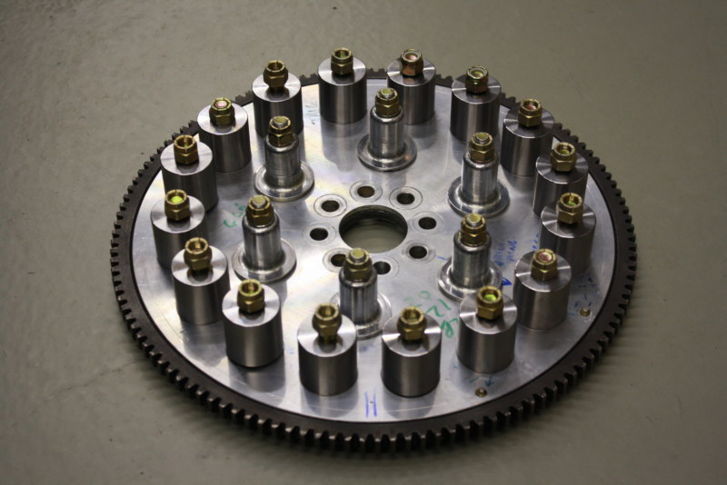
Modified flywheel showing weights and drive lugs
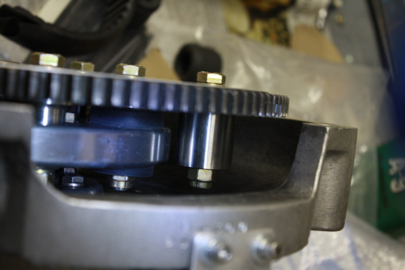
Closeup of weights and drive ring, bushings. Tight fit, has to clear crank sensor as well.
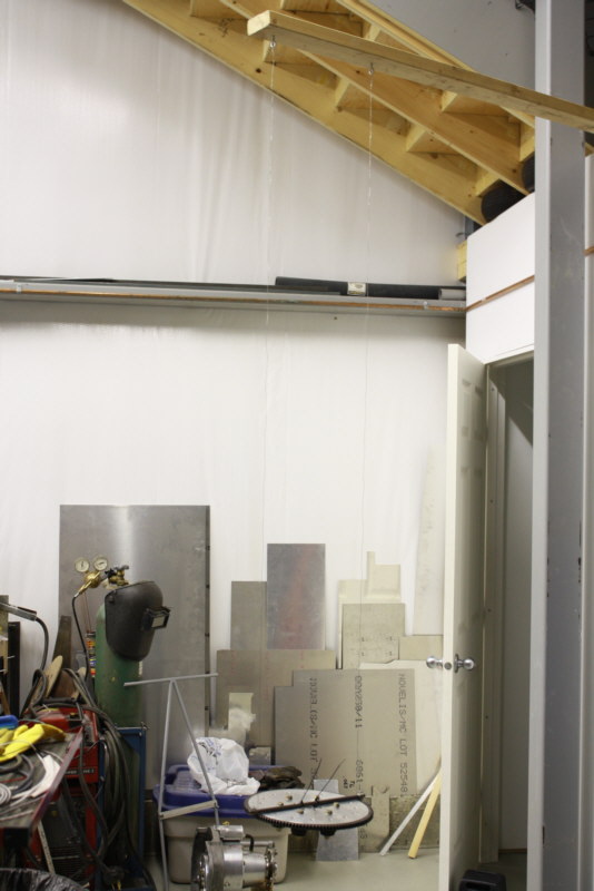
Rig for doing bifilar suspension test to determine inertia
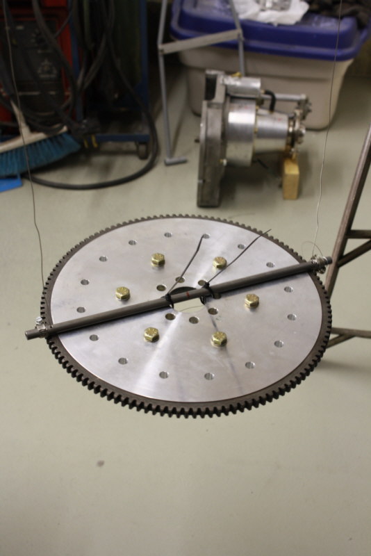
Flywheel suspended
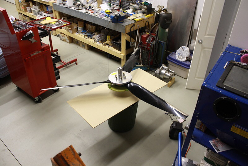
Propeller suspended for inertia test. Link to video of bifilar suspension test: http://s1105.photobucket.com/user/rv6ejguy/media/propvid0002_zpsb22bb67b.mp4.html?sort=3&o=1
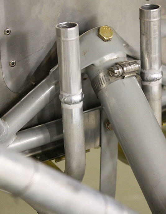
Coolant pipe assembly mounted
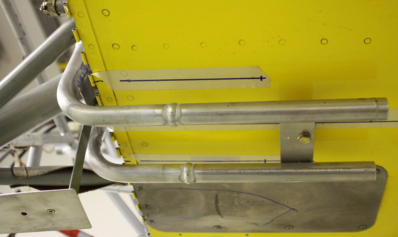
Coolant pipes attached to belly
02/17/13
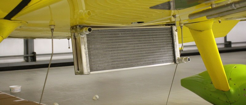
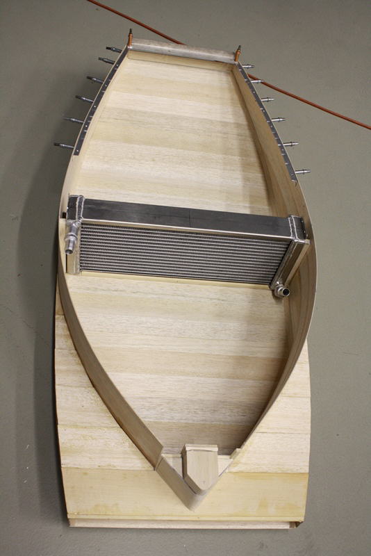
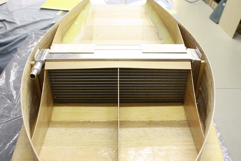
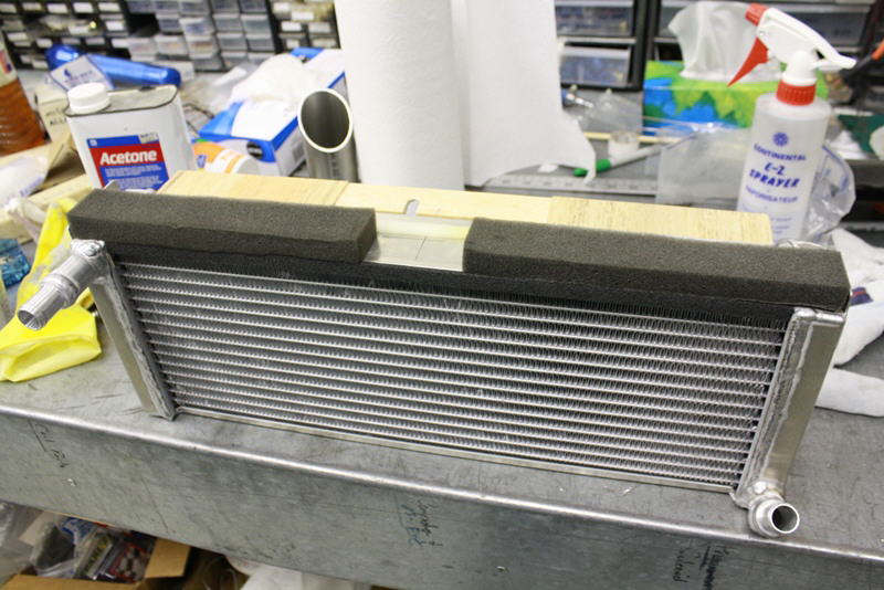
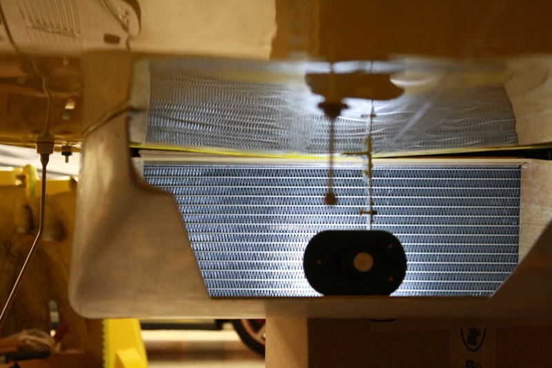
Rad hung in place
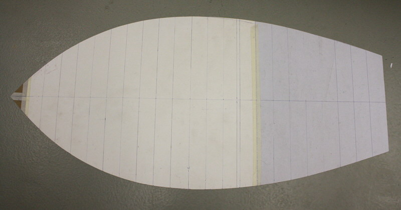
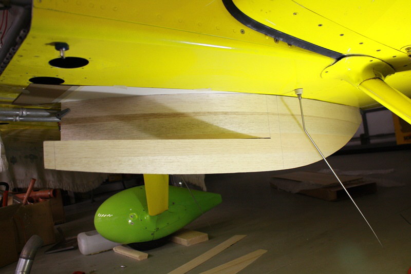
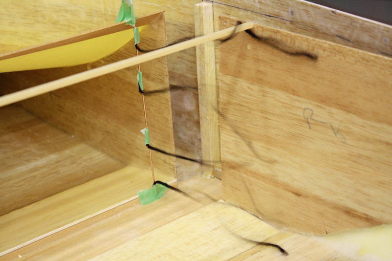
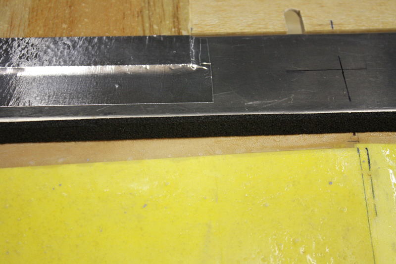
Layout of rad scoop shape on template
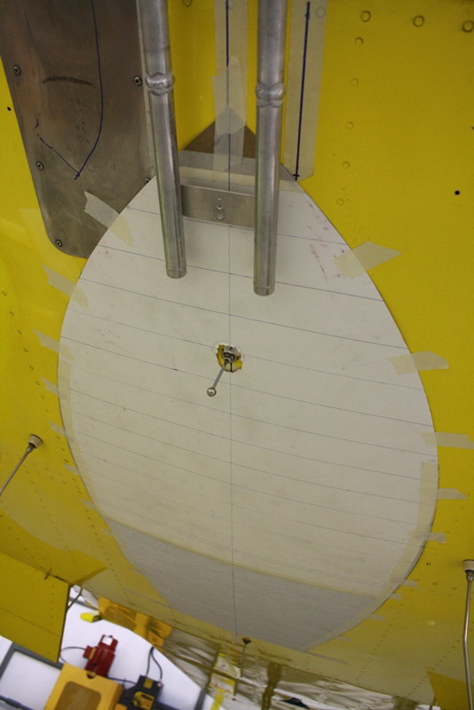
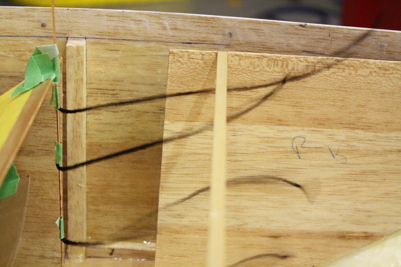
Template on belly
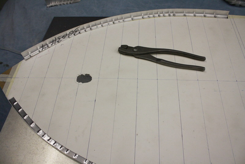
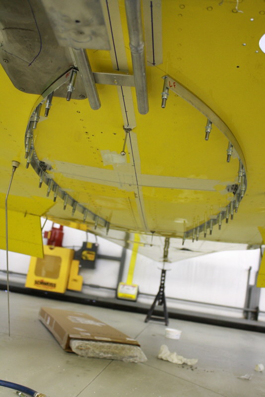
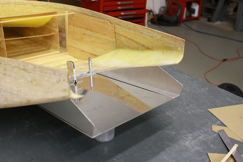
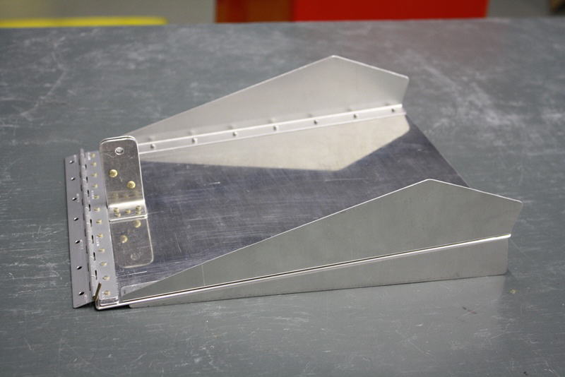
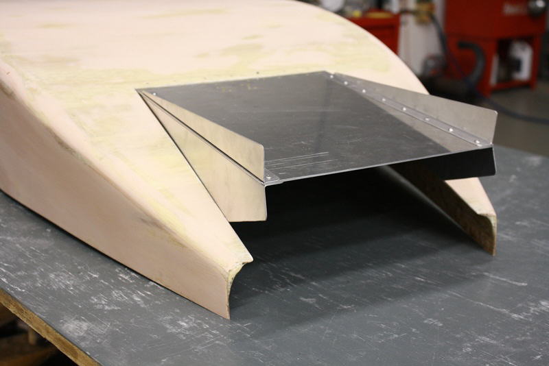
Rad mounting flange made to shape by fluting
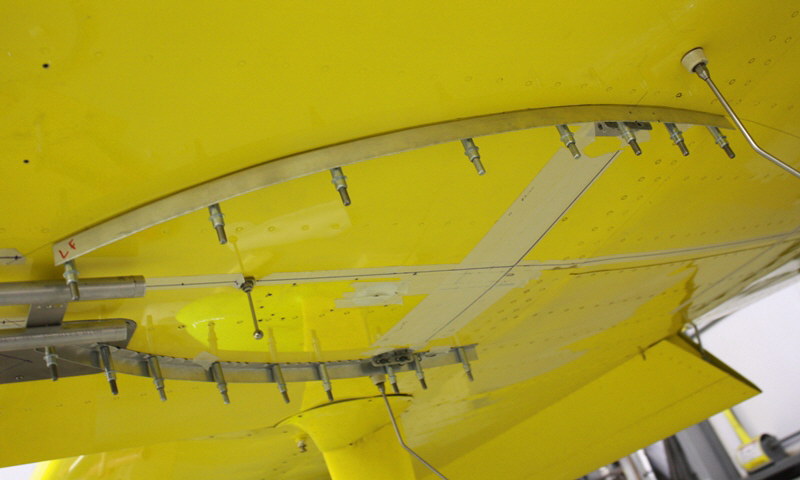
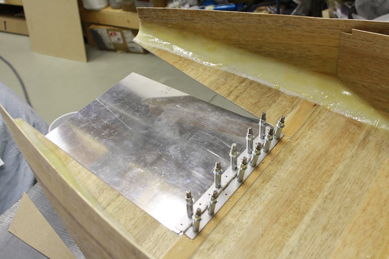
Front flanges clecoed to belly
All four flanges on belly. The front part of the fuselage is flat, further aft, the dihedral angle makes things more difficult.
02/21/13
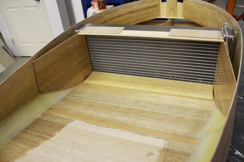
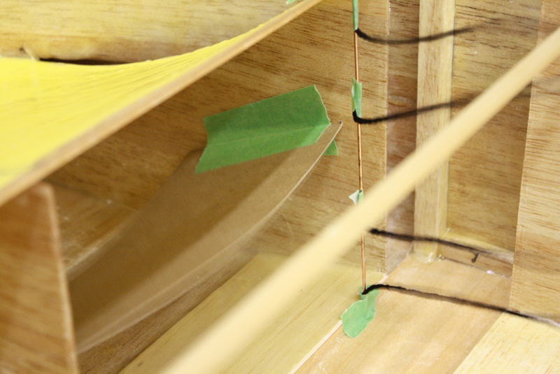
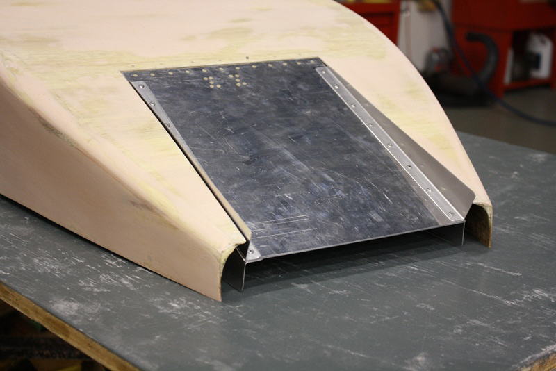
Rad scoop side profile shape
Side piece clamped in position
02/28/13
Drive bushings will be lubricated with silicone grease this time. When I tried to remove the gearbx last time, it took 45 minutes of struggle with prybars because the rubber bushings were so stuck into the drive ring and lugs.
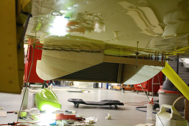
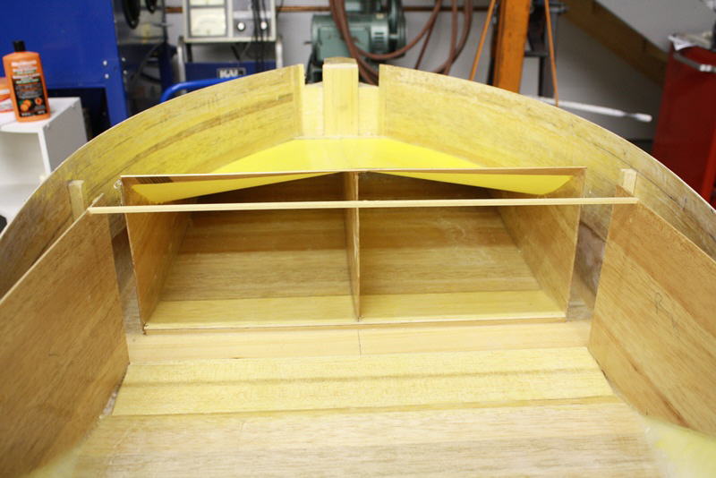
Rad duct taking shape looking forward from aft end
Rad duct from forward end looking aft
03/01/13
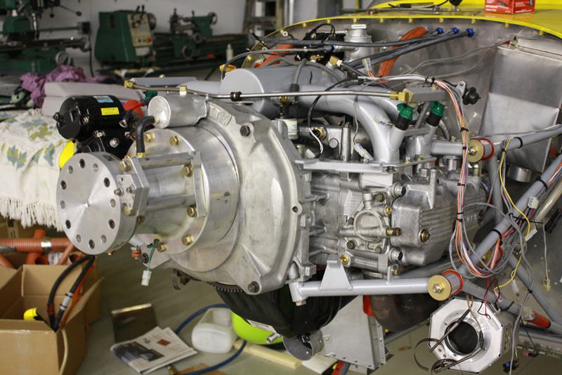
Engine back in the airframe
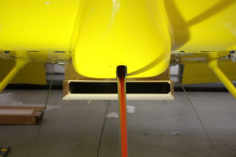
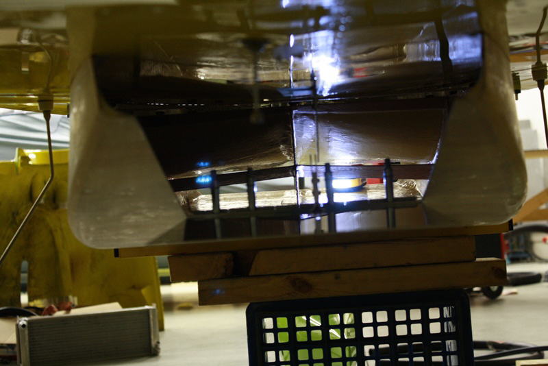
Rad scoop viewed from head on. Note that the original cowling air exit covers much of the frontal area of the new scoop. After removal of all the old protruding inlet and exit scoops, the new scoop presents about 20% less frontal area.
Mar. 3/13
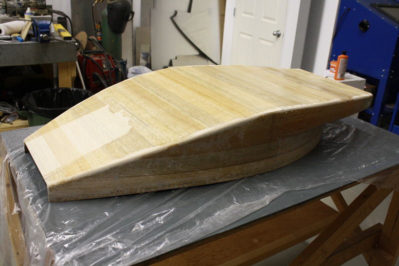
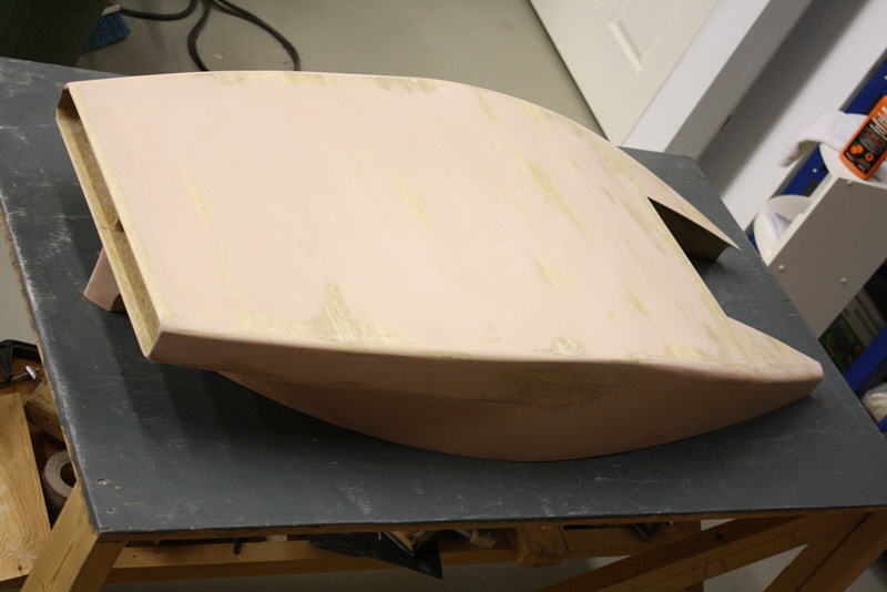
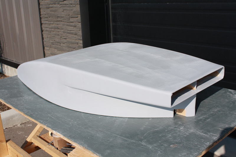
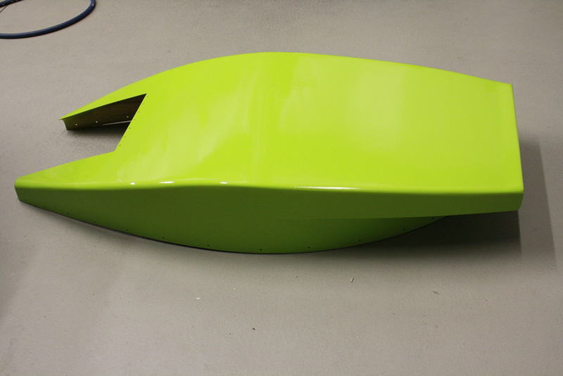
Finally pulled the basic scoop off the airframe to do work on the nose fairing and start the glass and foam work. Only weighed 1 pound 11 ounces here. Pretty happy with how it has turned out so far.
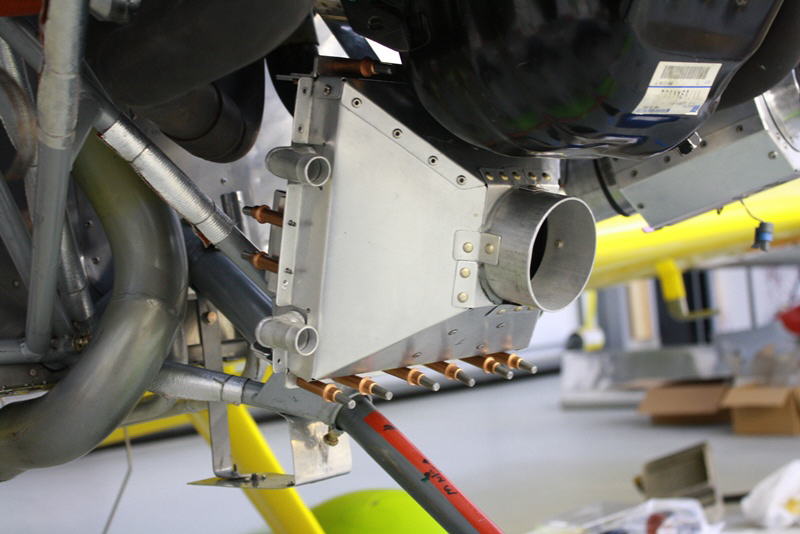
Cabin heat and secondary rad will be fed from a 3 inch straight facing duct just lower right of the spinner. Note diffuser inside the duct to spread the airflow out efficiently to wet the entire rad face. Developed on the flow bench.
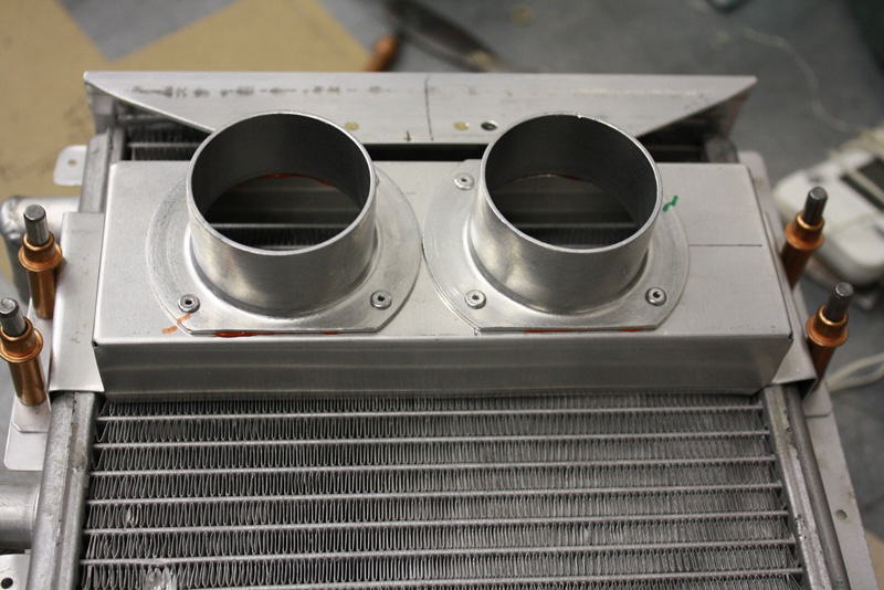
Twin 2 inch cabin heat connections
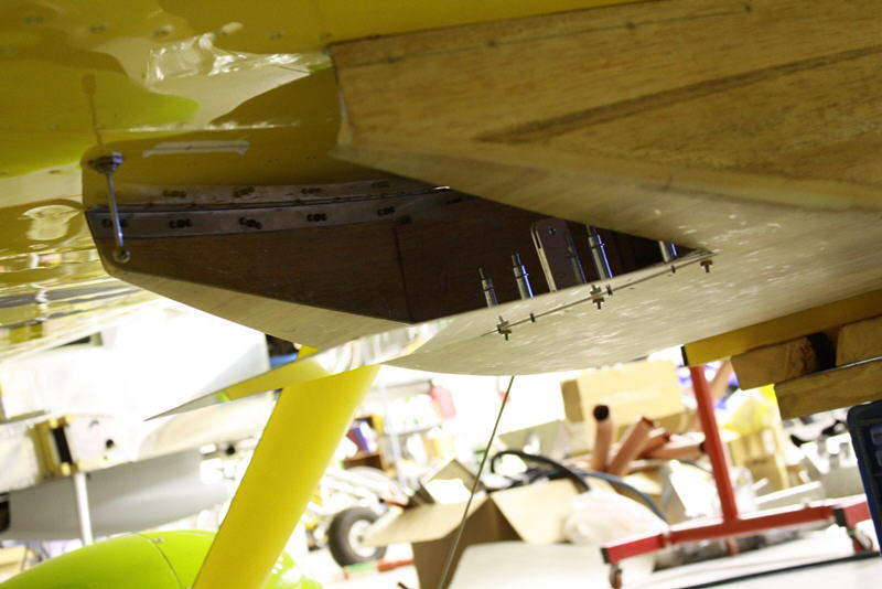
Rad mounts off nose gear support structure
Rear view
Rad scupper detail before sanding
Mar. 6/13
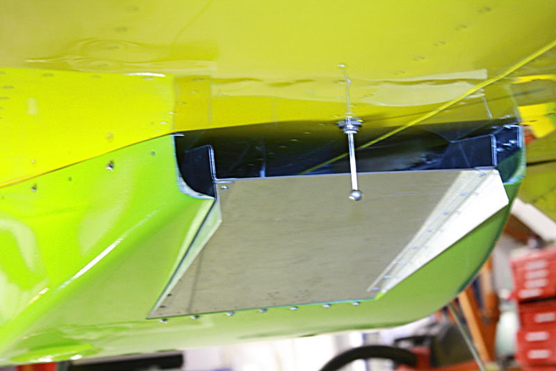
Rad sitting in scoop
Gearbox is back on the engine now
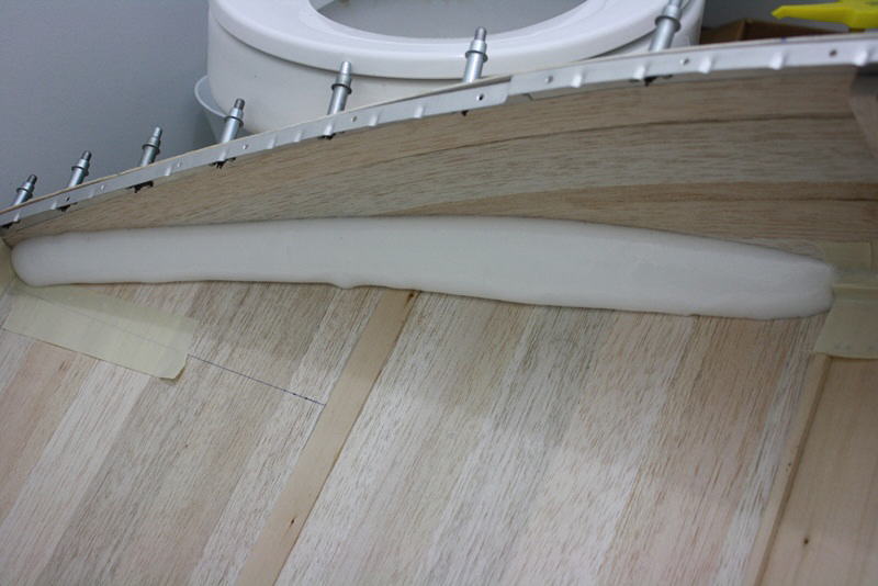
8 lb. pour foam added to scoop to allow generous exterior corner countours before glassing starts
Mar. 11/13
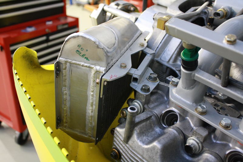
Intercooler mounted in new position
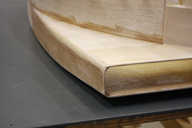
Radius sanded into aft corner of rad scoop
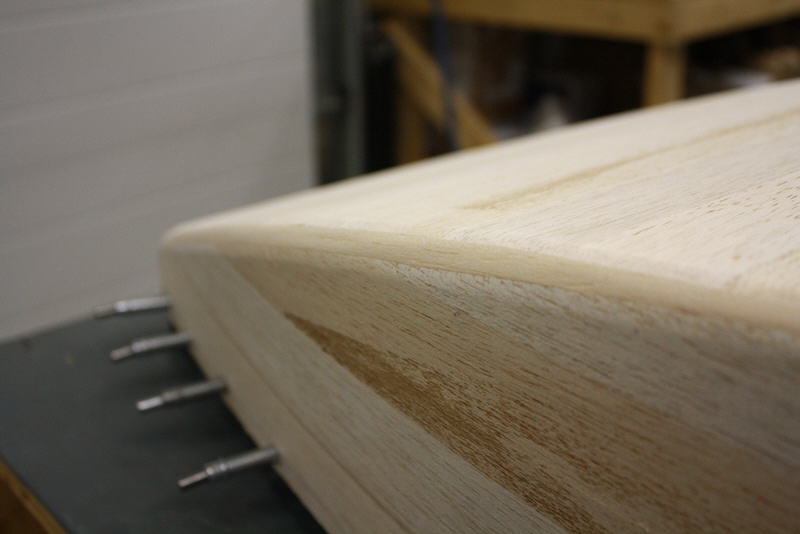
Front corner radius on scoop
Mar. 21/13
Intercooler plumbing top
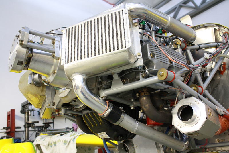
Intercooler detail lower
Glassing scoop. Long task
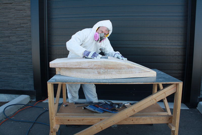
The story of my life lately, block sanding and more block sanding... fun
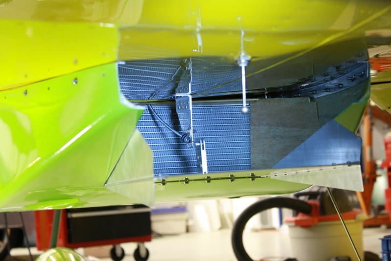
Rad in scoop with diffuser guides added. Note that the tanks and support structure are not in the airflow, just the rad matrix.
Exit guides added. We want smooth convergence of airflow after passing through the rad.
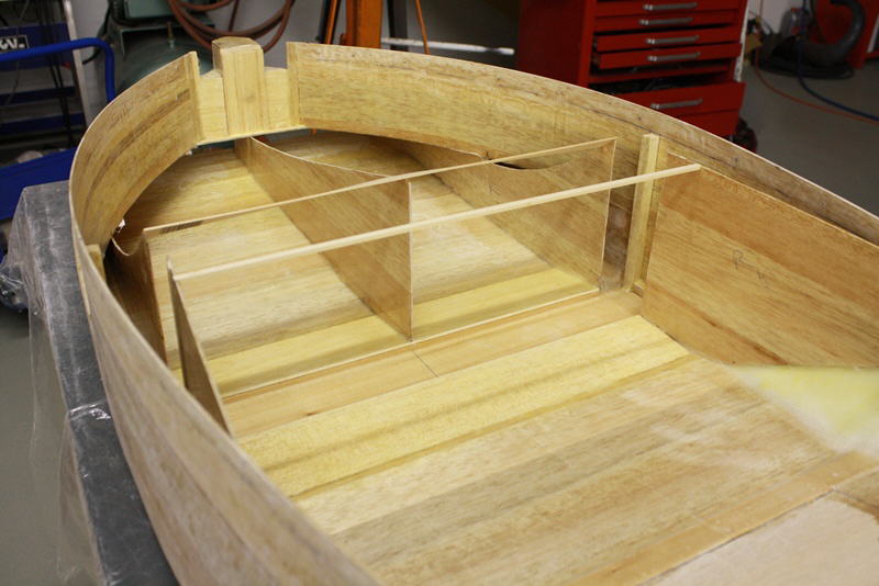
Diffuser shape detail
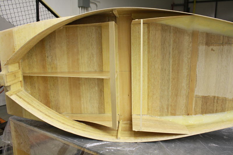
Shown on its side, you can see the smooth transition of shape through the rad
Still have to add the diffuser top and cut out the scoop for the exit door and make those parts. Then a lightweight fill and final block sand of the exterior. Over 200 hours into the scoop alone at this point. Many, many design/ construction details to work out.
Diffuser glassed in place, view from rear
Exterior of diffuser
Mar. 29/13 Airflow Testing
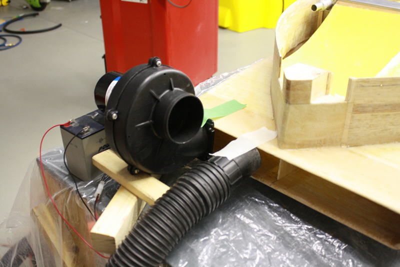
Twin blowers injecting air into the scoop to observe airflow patterns
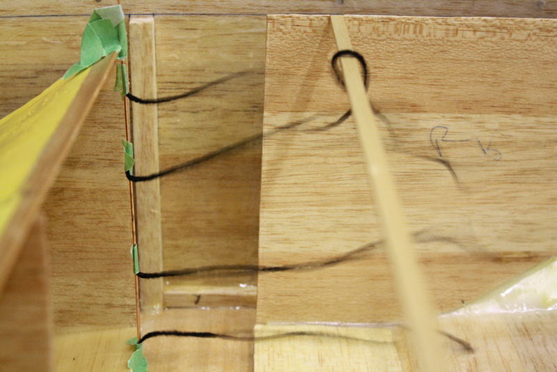
As expected, the airflow separates where the diffuser angle exceeds 7 degrees. Even with the rad in place, the flow was still turbulent in the upper, outer corner despite speculation on other sites that the damming effect of the rad would keep the air attached. The tufts show this is not the case.
View from back
With test cardboard guide vane in place, airflow stays attached and smooth in upper corner
View from rear showing the test guide vane, looking forward
Mar. 31/13
Rad door
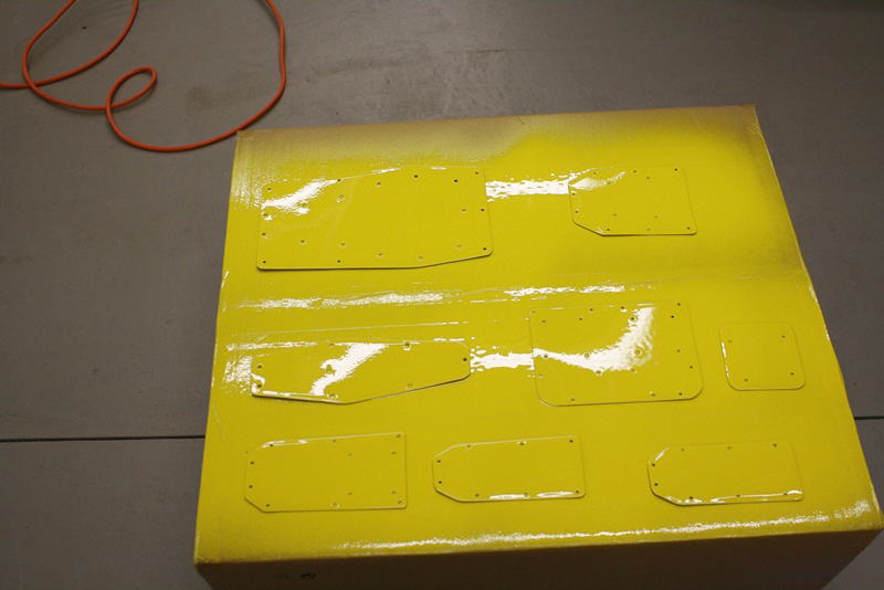
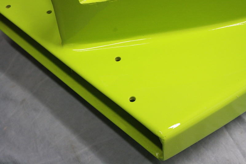
The weather was good so I finally managed to paint the various cover plates to replace all the air scoops on the aircraft
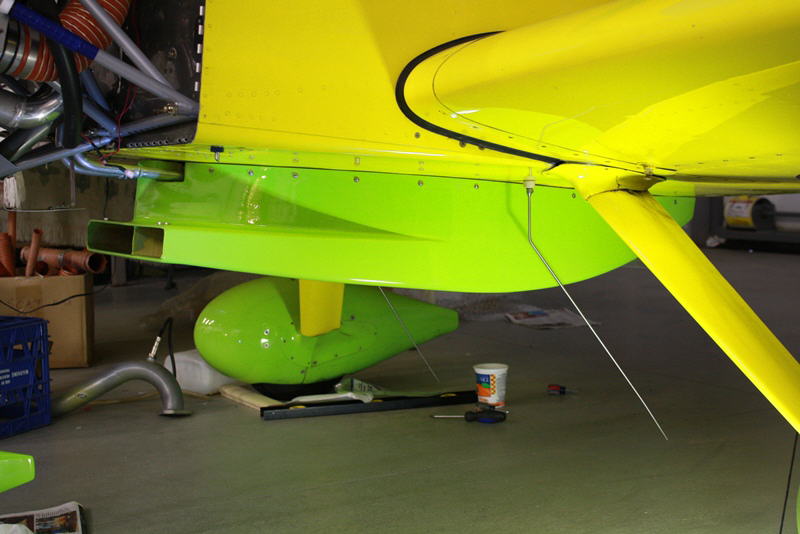
Rad scoop with exit door on plane
View aft forward through scoop
Door triangles resting place to seal exit flow
Scoop with fist layer of lightweight filler. More block sanding to come.
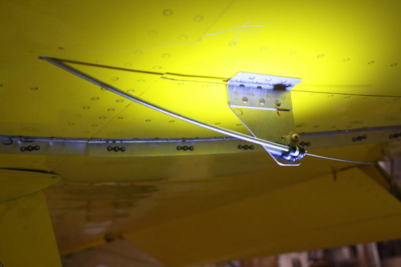
Exit door completed with cable horn and air capture wedges installed
April 3/13
Final sand of filler on scoop- about 10 hours total work. Scoop weighs just over 6 pounds.
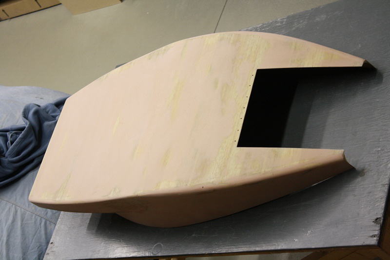
Scoop with exit door shown in open position
Door in closed position
April 8/13
Scoop with final coat of primer, one more block sanding to go before painting
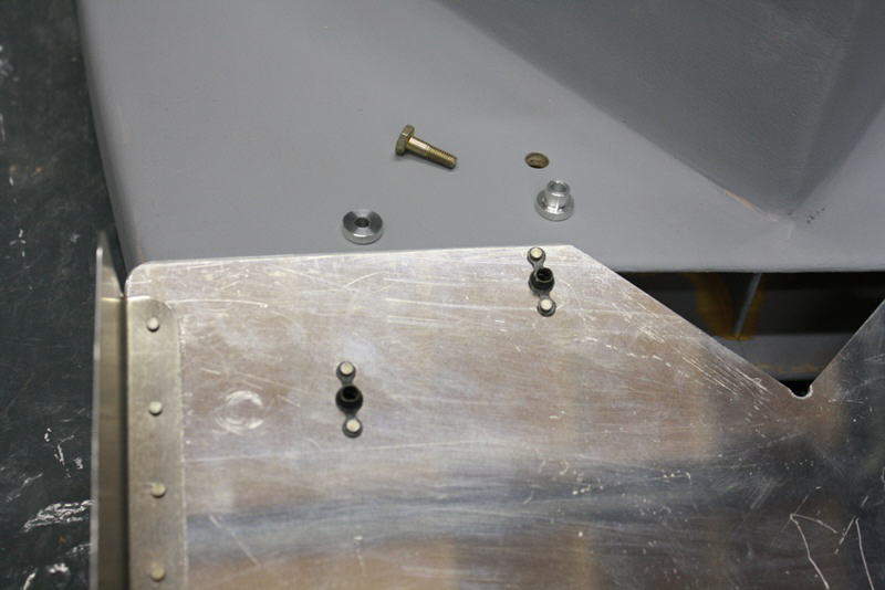
6061 hard points to mount splitter to scoop
Splitter mounts to top of inlet to guide air into the scoop and prevent hot air from the entering from the cowl exit
Reflection from splitter causes some visual confusion here perhaps
Head on view
April 24/13
Bracket for exit door cable
Foam seals rad edge to difuser totally
Foam seals against belly skin
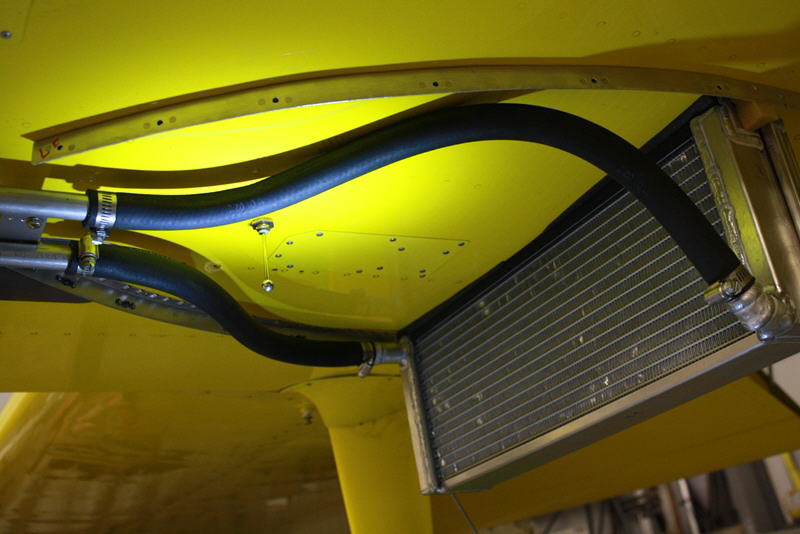
Rad hose detail
Foam seals against belly skin, note dihedral angle
View through scoop and rad from front, note guide vane
View from aft end of scoop, forward. black block is light
I finally installed the rad and hoses and took a deep breath as I worked the scoop up over the rad for a test fit. Many things to clear and seal tightly to. It worked! Now just waiting for a warm day to finish painting the scoop. I am just finishing off the last few details and will test run the engine soon. The end is finally in sight after over 5 months of constant work.
April 29/13
It's green! Not so happy with how the paint turned out, the wind came up both times just as I got the paint mixed up of course but I've reached my limit on sanding things after 250+ hours spent on this scoop. I ran the engine yesterday without the prop and all seems well. Prop is on now. Just a few tweaks and I'll get on re-weighing the airplane and start ground tests.
May 1/13
Scoop is bolted in place for good now. Inlet area is 29.5 square inches.
Door in open position, area 51.5 square inches. Note door control cable detail
Door in closed position, area 16.8 square inches
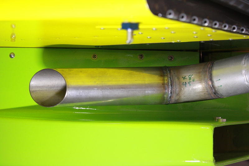
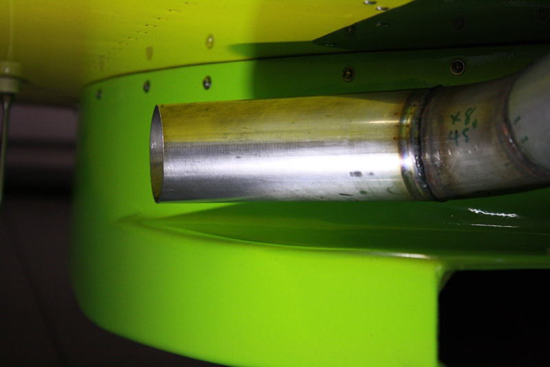
Exhaust pipe detail
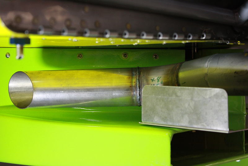
With splitter in place
So the airplane is finally back together and I just have to weigh it to find the new C of G and see how much weight was reduced. Glad it is almost done, this was a very long project- over 450 hours.
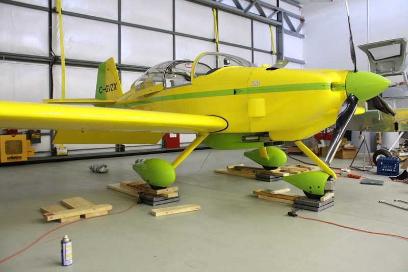
Weighing the plane. Canopy open to check level on rails, canopy was closed for actual weighing process. Weight was only 23 lbs. lower, a bit disappointing, was hoping for 30. Took a bunch of weight off the nosewheel which is always good and this was despite adding the 8 lbs. to the flywheel up front and removing the aft baggage bay radiator so we took a lot of weight out of the cowling and front cockpit area.
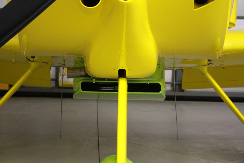
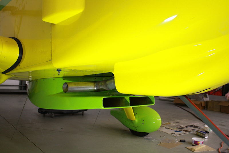
Front view showing everything in place, note the small gain in frontal area which was offset by the removal of 8 other external ducts and scoops totaling 20% more area.
May 5/13
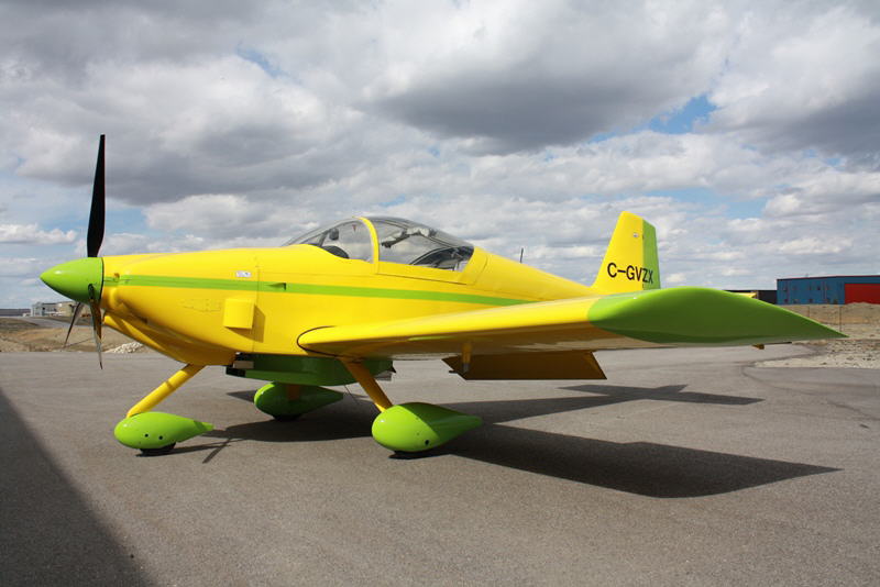
Back together in new configuration
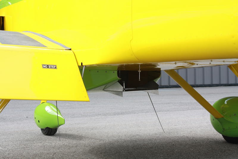
Exit door open
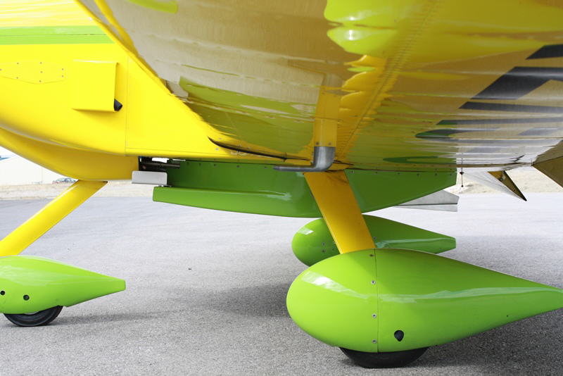
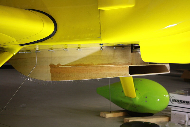
Radiator scoop from the side
Next RV6A page: Testing the new mods http://www.sdsefi.com/rv17.htm