

Other pages within the aircraft section detail various parts of converting the Subaru EJ22 for use on our RV:
EJ22 Engine05/10/00 Engine Mounting System
I purchased the Lycoming engine mount with the finish kit from Van's, mainly for the front landing gear mount. This is a precision piece and the mounting angle is critical. I must say that the fabrication and welding was some of the best that I have ever seen. Simply beautiful work. It was a shame to cut this up but it had to be done to fit the Subaru engine installation.
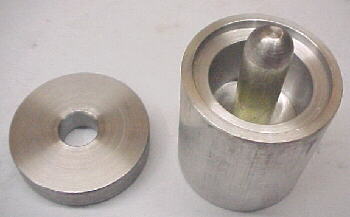
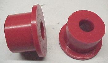
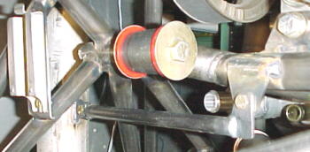
After trying to source proper engine mount bushings for the project, I decided to machine a mold and have my own urethane bushings poured. This turned out to be cheaper than buying off the shelf rubber ones surprisingly.
I have spent several hours looking at the best way to mount and brace the engine to the airframe and finally have a rough idea on how to do this. Time to get out the lathe and TIG.
05/21/00
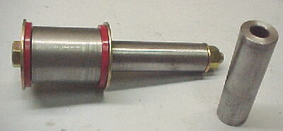
I got my engine mount bushings back from the urethane shop. They look good and I can get back to work on machining the steel captures for them and on the mount structure
05/29/00
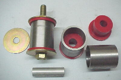
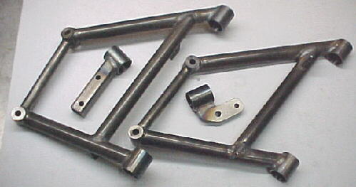
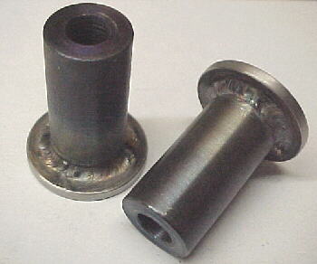
I machined up the bushing captures and bolt sleeves.
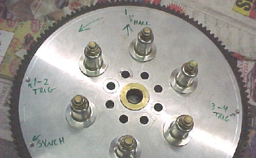
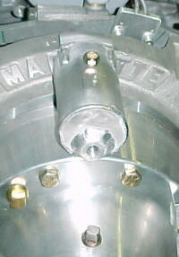
Next I had to install the starter ring gear onto the Marcotte flywheel. This took about 2 hours. After much struggling, I finally decided to put a substantial radius on both the ring gear and flywheel. I then cooled the aluminum flywheel in cold water and heated the ring gear to about 300F with a propane torch. I finally got it started fairly straight then hammered it into submission with a nylon tipped hammer for about 15 minutes. Fun stuff.
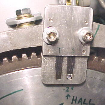
I bolted the flywheel in place and figured out the best place to mount the crank sensor. Once marked, I calculated the position of the trigger and synch magnets for the SDS unit. Shallow holes were drilled and the magnets epoxied into place.
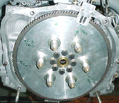
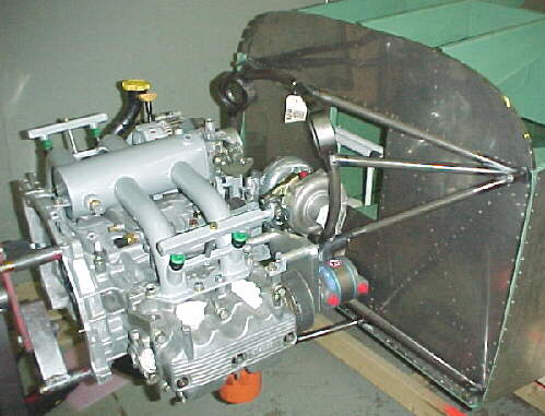
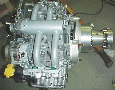
Finally, I installed the flywheel with grade 8 washers under the supplied bolts which were locktited and torqued down to 45-50 ft./lbs. The redrive was then bolted to the engine. I modified my engine stand to hold the assembly from the prop flange so that the cowling may be easily checked for fit and clearance.
06/05/00
While planning tube layouts for the engine mount, I discovered some more drawing inaccuracies on the plans. Drawing 61 shows the centerline spacing of the outer engine mount holes at 19.375 inches. Drawing 22 makes this measurement 19.250 inches. Drawing 25 shows a dimension of 19.375 on one part from the bottom outer hole to the top of the gusset and 19.325 on another view. The actual mount was made to 19.250 spacing, the firewall was drilled from Van's at 19.500 inches. It took a lot of flexing to get the factory Lyc mount bolted up to the firewall. It appears as though the factory is drilling the holes incorrectly based on the mistakes on the plans. Normally, people installing the Lycoming would just bolt it up and forget it, despite the 1/4 inch error. In trying to determine the actual propeller thrust line, I discovered the errors. The thrust line is more like 5 inches below the top bolt hole centerline, not 4.75 inches as stated on drawing 61. If the factory had drilled the top holes even 1mm higher, you could not thread the nuts on to the top bolts as they would have hit the gusset structure. I'd like to know if others have seen the same things on their kits.
06/12/00
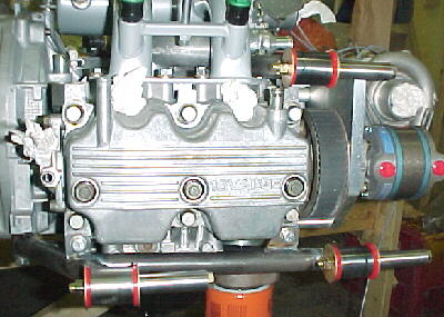
I machined the engine pickup tubes from .75 OD .375 ID DOM tubing. These bolt to the engine mounts with 3/8 grade 8 bolts and the main bearer tubes will be welded to them.
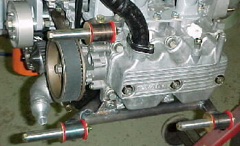
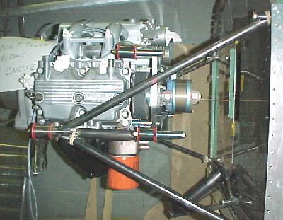
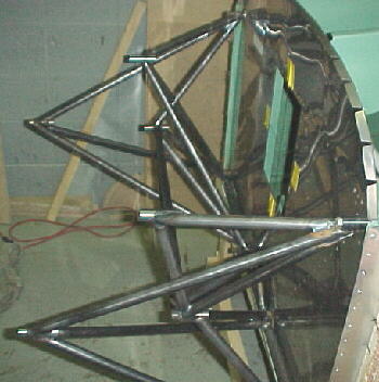
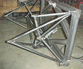
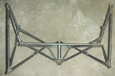
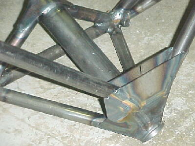
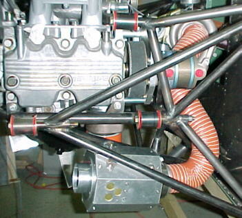
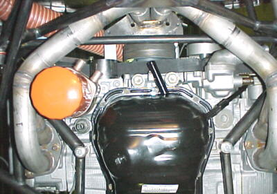
I started welding the main support structure which is attached to the original factory pickups with two 10 X 1.25 bolts on the block and the two new drilled and tapped 5/16 NC holes in each head. These were constructed mainly from 1 inch OD .058 wall 4130 tubing. Head tabs were .1875 4130 plate stock. Block pickups are 1 inch OD DOM bosses. All assemblies are TIG welded.
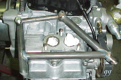
Left side
Left side
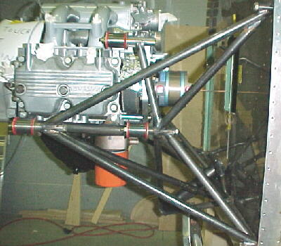
Right side
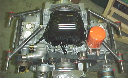
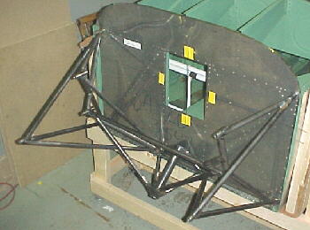
Bottom view
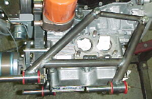
Bottom left close up
06/13/00
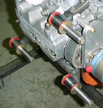
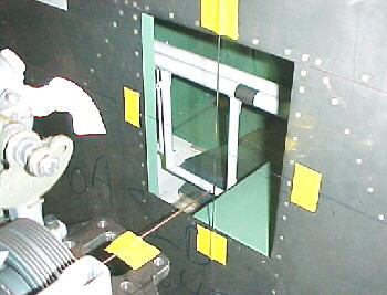
I machined the top firewall pickups from .750 DOM tubing and TIG welded a backup washer to it. The assembly was then machined.
06/19/00
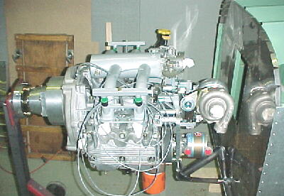
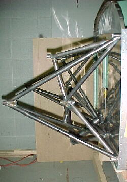
4 hours were spent levelling out the fuselage and aligning the engine correctly. The engine is offset 1.25 degrees to the right just as the Lycoming is. This matches the fiberglass cowling which has the spinner flange offset slightly. After this was done, it was time to start cutting tubing. .750 X .049 4130 is used for the main mounting tubes. Filing the tubing to fit the multiple angles is time consuming and the order of tube placement should be planned out prior to starting. Tubing layout needs to ensure proper triangulation and support, especially on the nose gear pickup tube.
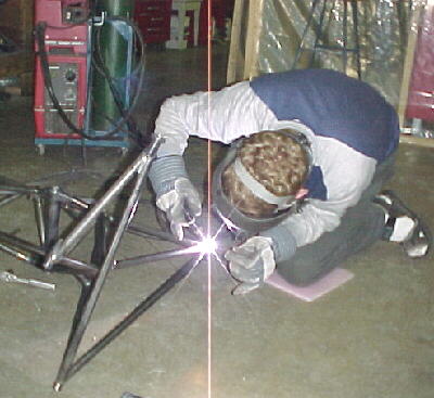
06/26/00
This takes a long time. I finally had all the tubes tacked in place and removed the mount for final welding. The mount was bolted to a heavy steel frame to prevent warpage.
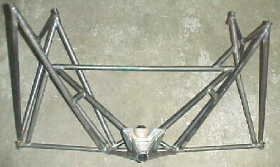
06/28/00
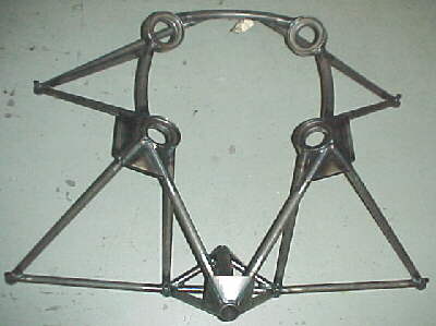
The mount is now substantially done except for powder coating. It took 83 hours to engineer and build. Weight for the 3 components is about 21 lbs vs. 14 for the Lycoming mount. 31 feet of 3/4 tubing was used. 6 engine pickup points are used which are fully triangulated. This mount is exceptionally strong and offers better nose gear support than the factory mount.
11/30/00
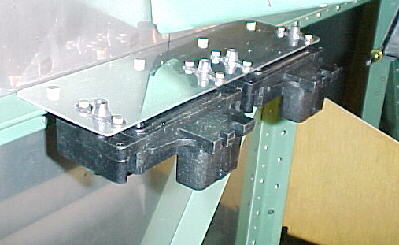
I fabbed and riveted a bracket to the upper firewall angle to mount the twin MAP sensors for the engine management system.
12/29/00
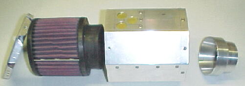
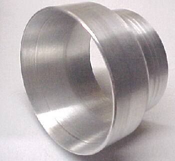
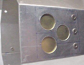
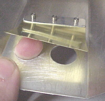
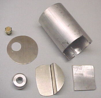
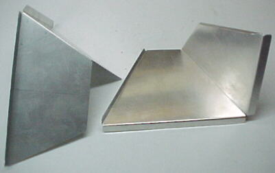
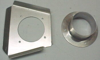
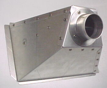
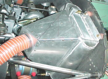
After considerable planning and an evaluation of available space, I constructed an octangonal plenum box from aluminum to surround the K&N air filter. I also machined an adapter to step down the 3 inch air filter neck down to the 2.5 inch SCAT hose diameter which will feed the turbocharger. Twin brass reed valves are incorporated into the plenum for an automatic alternate hot air source in the event that the main feed ices over. Cold air will be ducted from the left radiator plenum via 2.5 inch SCAT hose. The airbox plenum will be mounted to the lower left engine mount tubes.
01/21/01
The air filter assembly is mounted to the lower left engine mount tubes via 4 small weld on tabs.
01/22/01
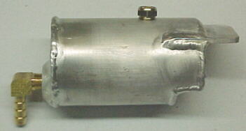
I fabbed a small vent tank for the Marcotte redrive from 2 inch 6061T6 tubing. This is connected with fittings and hose to the redrive vent hole and permits venting air pressure without losing oil from the unit.
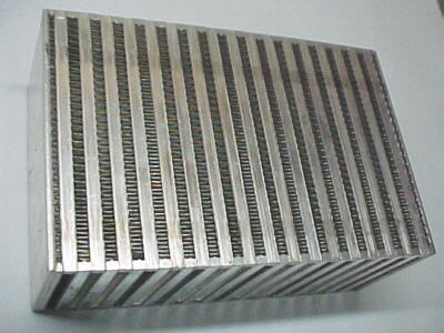
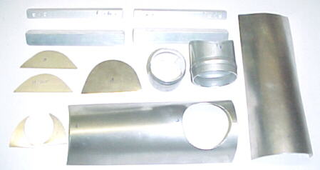
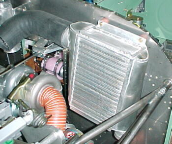
The intercooler consists of a Spearco core measuring 6 X 9 X 3.5 inches and the associated sheet metal tanks and snouts which I fabricated from 6061T6 sheet and tubing. The material must be annealed by heated to 450F so that it can be formed without fracture.
02/05/01
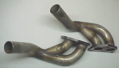
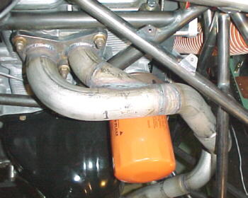
After much contemplation, I started fabricating the turbocharger header. This is primarily constructed from 1.75 OD X .065 wall, 321 stainless tubing and mandrel bends. This is about the best material available for withstanding the high heat outside of Inconel which is even more expensive and harder to work with. I see other people making turbo headers out of .035 or even .049 and this just scares me. Stainless has a 50% higher coefficient of expansion compared to mild steel so bellows or slip joints must be encorporated to prevent cracking. The material saws well but is difficult to file. It also must be back purged with argon when TIG welded to prevent the back of the weld from crystalizing. This is a real pain.
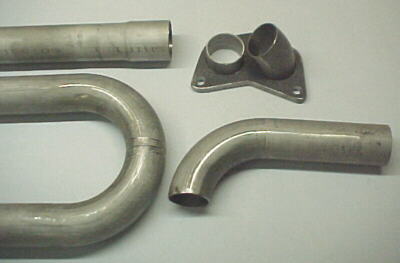
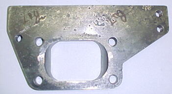
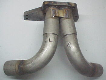
1/2 inch thick, mild steel turbine inlet flange/mount
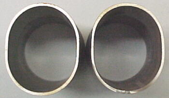
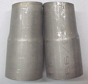
Turbine inlet pipes with slip joints formed to fit inlet flange
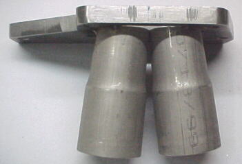
Pipes tacked to flange
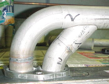
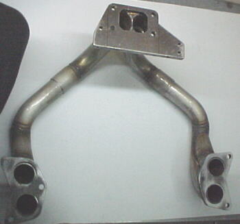
Head flanges with pipes mocked up
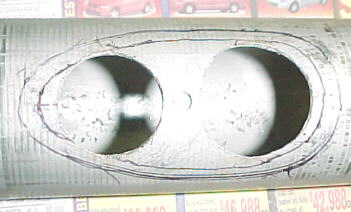
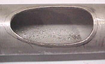
Primary tubes with hole outline marked, hole sawed pilot holes and die grinder finished shape
02/12/01
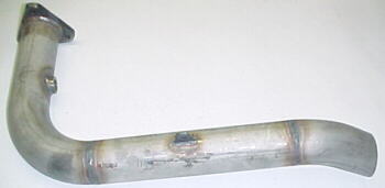
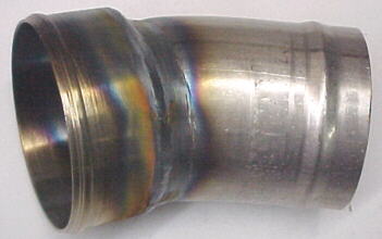
The turbine discharge pipe is made from .049 wall 2.25 inch OD 321 stainless. It incorporates a 304 stainless O2 sensor boss and an articulated 4130 tubular stay to reduce ringing while still allowing the pipe to grow in both directions. Exhaust exits at 45 degrees.
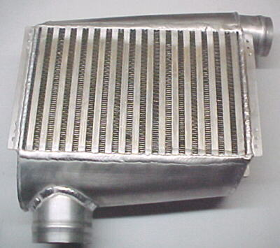
The intercooler is mounted to the firewall with -3 bolts, backup angle reinforcements and nut plates. It stands off the firewall about 1/2 inch to allow air to exit through the core. The intercooler weighs just over 5 pounds and the whole assembly with piping is about 8.5 pounds.
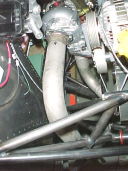
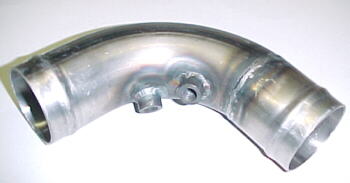
I had to build an adapter to go from the throttle body to the 2.5 inch intercooler discharge pipe. This involved a machined piece and a 2.5 inch, .040 wall mandrel bend. The adapter and intercooler were joined with a Goodyear 60832 radiator hose for vibration isolation. These have been well proven in race car applications to reliably withstand up to 70 inches of manifold pressure. All hose connections are beaded for reliable retention.
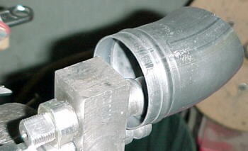
The compressor discharge pipe was made from 2 inch, .040 wall mandrel bends and tubing. It incorporates 1/8 NPT threaded bosses for a temperature sensor and the wastegate control pressure tap. It is connected to the intercooler by a Goodyear 60829 rad hose.
02/19/01
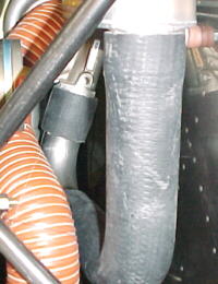
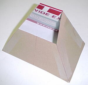
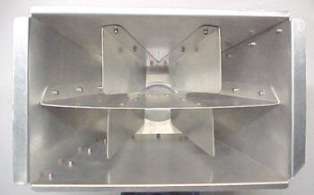
The intercooler diffuser duct was constructed from .028 aluminum sheet. I made a cardboard mockup to be sure that everything fit in the confined space available. The duct was originally fed by one piece of 2 inch SCAT hose (later changed to 2). It was necessary to diffuse the airflow from the hose out to cover the full surface of the intercooler core. This was accomplished with 5 guide vanes riveted the inside to turn and spread out the flow. This was confirmed on the flow bench. The duct was assembled with stainless steel rivets and is held to the core with four #8 screws.
02/26/01
I finished fitting and welding the exhaust system. Total system weight is 13 lbs. for both the inlet and outlet systems including the 1/2 inck turbine inlet flange and 3/8 head flanges.
08/06/04
From flight testing we have established the following limitations for our EJ22T engine:
Max takeoff power: 5300 rpm/ 42 inches
Normal takeoff power: 4600 rpm/ 38 inches
METO power: 5000 rpm/ 35 inches
Climb power: 4800 rpm/ 35 inches
Max cruise: 4600 rpm/ 30 inches
Medium cruise: 4400 rpm/ 25 inches
Economy cruise: 4400/ 22 inches
Max compressor discharge temp: 100C/212F
Max intercooler discharge temp: 55C/131F
Max oil temp: 120C/248F
Max coolant temp: 110C/230F
Max EGT: 760C/1400F
Max redrive temp: 100C/212F
Fuel Flows
Leaned to short of 1400F EGT, we see the following fuel flows:
Climb power- 4800/ 35 inches- 72 lbs./hr.- 12.0 US Gal/hr.
Cruise- 4600/ 30 inches- 58 lbs./ hr.- 9.7 US Gal/hr.
Cruise- 4400/ 25 inches- 47 lbs./ hr.- 7.8 US Gal/hr.
Cruise- 4200/ 22 inches- 39 lbs./ hr.- 6.5 US Gal/hr.
08/19/04
During our annual inspection, with 97 hours on the engine, compression tested well. 2 spark plugs showed above average wear to the center electrode so they were changed.
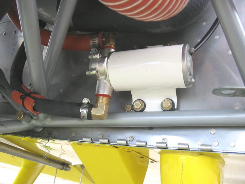
04/27/08
We switched the turbocharger scavenge pump to a lighter gear type pump after getting tired of cleaning off the belly from the old pump always leaking oil. So far the new one is totally dry, 3 pounds lighter, quieter and draws about 1/2 the amperage.