


Last update: July 29/24
If you have a question you'd like answered about SDS fuel injection just drop us a note by E-mail to racetech7@proton.me
This page is mainly for automotive information, mostly applying to EM-1 through EM-5 systems. For aviation specific information please click. Aircraft
Tech Articles
Tuning on a DynoJet
Sequential Injection Realities
How to Build a Surge Tank
HP vs. Injector Flow Rate
Fabricating an Intercooler
Fabricating a Turbo Header
Start and Warmup Programming
Fuel Values and Cams
Pushing it Too Far
Phantom Problem
Engine Map Examples
Airflow, Fuel Flow, HP Formulae
Hints on Hall Sensor/Magnet Mounting EM-5 and EM-4
How to Fabricate an Intake Manifold
Tuning TPS Only Systems
How Much Power?
Ignition and Combustion
Fuel Octane vs. Horsepower
Importance of Fusing Components
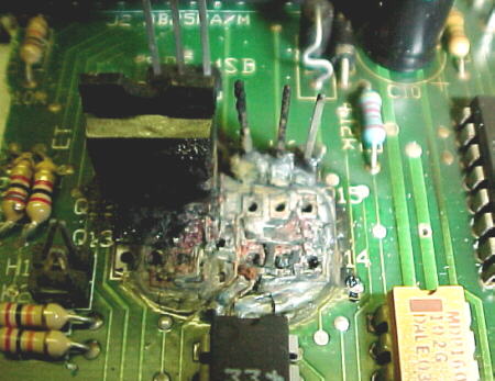
Many of the damaged components that we have returned to us could have be saved if the user had installed proper fuses as recommended in the manual. This applies to 4F coil packs where a 7.5 or 10 amp fuse should be installed and a 15 amp on 6F coil packs. If you start blowing a fuse, DON'T install a bigger one, find out why it's blowing first. Installing a 15 or 20 amp fuse on the coil pack offers no protection and will result in fried drive transistors or fried coils if something goes wrong. We recently had an ECU returned to us in which a huge fire had started inside and completely ruined it (photo below). Obviously very high current flowed through this component for a long time to cause this type of damage indicating an unfused component somewhere along the line.
Remarking Magnet Ends
Some people have rubbed off the blue marking on their magnets while handling and mounting them. To find the marked end again, follow this procedure:
1. Power up the ECU with the Hall sensor plugged in
2. Wave a magnet over the black square on the Hall sensor (E) or the blue marked black square element (F) with the programmer in the magnet window screen.
3. If the display does not read SEEN, flip the magnet over and try again. The magnet end facing the trigger element of the Hall sensor which makes the display change to SEEN is the blue marked end.
4.Mark this end.
5. With the marked end facing up, the magnets will all stick together in a line with the marked end up. Mark all these ends accordingly.
Resistor Spark Plugs
For engines experiencing RPM ERR codes which cannot be solved by other means such as moving Hall sensor cables or changing spark plug wire types. You MUST use resistor type spark plugs with SDS.
Mystery Timing/ Detonation Problems on Engines With Rubber Damped Crank Pulleys
We have seen several cases of unexplained detonation and ignition timing changes. These were caused be slipped harmonic balancers where the rubber portion has lost its bond on the inner or outer pulley sections, causing the outer section to rotate relative to the inner section fixed to the crankshaft. It's worth verifying that TDC on the pulley is actually TDC on the engine, otherwise your ignition timing may be way off.
08/13/03 Concerns When Using Multiple Throttle Plate Induction Systems
We have had many calls from people running induction systems with one throttle plate per cylinder and independent runner manifolds using our systems on street driven vehicles. These people often complain of marginal driveability under low throttle openings and/or low rpm conditions. We have never recommended the use of our systems with IR manifolds for the street, especially when using a MAP sensor for load sensing. The situation is worsened when combining this hardware with hotter cams, resulting in an unacceptable vacuum signal for the MAP sensor. This is race type hardware, generally not suitable for street use unless the user accepts decreased driveability and/or switches to TP load sensing
The vacuum averaging canister required on IR applications will result in a lower than actual vacuum reading than would be seen on a plenum type manifold setup due to the fact that all the ports which don't have a valve open to establish flow are leaking air into the cannister. There is no way around this and this is the reason why few OEMs use speed density EFI systems with this hardware, they usually use an airflow/mass sensing system instead. Also, 95% of all production cars use plenum type manifolds. Our general rule of thumb for using a MAP sensor in any street application is a minimum of 15 inches of idle vacuum. Less than this any you may have to switch to TP load sensing with its own disadvantages. Race stuff on the street is usually fraught with compromises often not worth the gains in power after you live with the car for a while. Big, open mufflers bore into your brain on the highway, hot cams make the bottom end, driveability, fuel economy and emissions suck, huge turbos have big lag and high compression/high boost leads to detonation and broken engines running on pump fuel. Use your noggin here and don't expect miracles.
Replacing Magnets
We have a fair number of people incorrectly install the magnets on E and F systems the first time. Some people attempt to pull the magnets out by heating the epoxy with a torch or heat gun. Heat over 250F will damage the magnets and reduce their flux strength. These should not be re-installed. Use new ones. It is important to remove all of the magnet fragments before installing new ones also. The EM-4 manuals give plenty of detail on how to install and verify proper magnet placement. Follow these directions exactly and you will save yourself a lot of trouble. Don't rush this job! Contact us if you are unsure before gluing them in.
Care and Feeding of F Coil Packs
We see a fair number of F coil packs damaged by 4 main causes:
1. No fuse on red power wire
2. Water damage to circuit board
3. Vibration damage to circuit board
4. Improper magnet or Hall sensor mounting
It's easy to avoid damage by following the manual. Use only a 7.5-10 amp fuse on the red power wire on the 4F coil pack (10 amps on 6F coil packs). Don't wail on the coil pack with a pressure washer or submerge your vehicle. Don't mount the coil pack to the engine. Make sure magnets are mounted correctly, sensor is aligned and sensor mount is REALLY stiff and strong.
It Won't Start!!
We have had many tech phone calls where the customer said the engine would not start. In all cases, the user reported that they had gone through all the troubleshooting sections without result. This section has been refined now for almost a decade and is very complete. IF you actually verify compliance with ALL points in the troubleshooting section, there is a 99.5% chance that the engine WILL start. Latest problems were no fuel delivery (item 13) and improper camshaft timing (item 16). Don't assume, actually check it and tick it off.
Plug Gap on High Boost Applications
On engines operating under high boost/rpm conditions it may be necessary to reduce spark plug electrode gap to as small as .020 (0.5mm) to ensure proper ignition.
Coil on Plug Setups
Many people have asked if they can use the factory coil on plug ignition hardware with our F systems. Using the standard F coil packs is often a better idea. We can work with some Subaru COP units, notably EG33, EZ30, STI, GM, Ford, Honda and Nissan. We need to have a pair of coils to evaluate on the bench to determine compatibility and charge times for those we have not already tested.
Fusing on F Systems
After some recent mysterious coil pack failures and returns, we conducted some more destruction testing of the F coil assemblies. It proved impossible to damage the coils or amplifier circuits by pulling plug wires off (not recommended). It was found that the proper fuse would protect the coils or drive transistors from failing even if power is left on somehow (this should be protected against by software limits). NEVER remove any ECU ground wires with power on. This can leave the outputs on and fry the coil pack.
Our recommendations for F coil packs:
1. Do not mount the coil pack to the engine.
2. Do not point a hose or pressure washer nozzle at the coil pack. Cover with a bag when washing.
3. Try to mount the CP with the wires facing down. This allows water to run down the wires, not into the case.
4. ALWAYS install a 7.5 or 10 amp fuse on the red power wire running to the coil pack (15 amps on 6F coil packs).
5. Do not connect coil power directly to the battery. It should go to switched 12V.
6. Never test for spark by pulling the plug wires off. Use the procedures on this page or in the manual.
7. Never pull computer, coil pack or injector ground wires off with the system powered up. This leaves outputs ON and can fry components like the coil pack or blow the injectors open and fill the cylinders up with fuel.
8. NEVER connect the coil pack power or ground wires UNTIL you have verified that all magnets are aligned and being seen for 3-4 degrees of crank rotation.
VVT, VTEC
We get many enquiries about whether SDS will drive certain variable valve timing or variable intake plate systems found on modern engines. At this time, we can only drive single stage (on/off at a certain rpm). This includes early VTEC, TVIS and VVT systems. The rpm switch option will not properly control iVTEC, multi stage VTEC, VVTi, VVTLi, VVL or Vanos.
It Won't Start!
We have recently had several people report no starting situations upon installing our systems. After much head scratching, these problems were traced to varnished up injector nozzles. In all cases, the engines had been sitting for 1.5 to 3 years. If you have spark and fuel pressure and the engine won't even kick, suspect plugged up injectors. Send them out for cleaning or invert them and put a few drops of acetone on the tips. Remember what the manual says "99% of all running problems are due to mechanical deficiencies". Don't blame the electronics until you have checked out the mechanicals. Don't assume anything when trouble shooting.
Another problem we have seen a few times is camshaft timing, especially on newly assembled engines and offroad engines where sand ingestion between the belt and sprockets is common. Check ignition timing, cam timing marks, compression and fuel delivery before calling us.
Lastly, check all your fuel cut limits. We have seen this problem many, many, many times. MAP and RPM fuel cuts and low values set wrong (low rpm, low vacuum) will ensure that the injectors don't open during cranking.
Fusing/Wiring
Many people seem unsure about the purpose of fusing various components. The first thing that should be clarified is that fuses are installed to protect the wiring primarily, not the device, although is some cases, a fuse blowing may mitigate damage to drive transistors and coils for instance. Fuses are selected on the basis of current draw. Wire gauge is selected on the basis of current draw vs. the length of the wire. Longer run lengths require larger gauge wire. You should never use smaller than 18 gauge wire to connect the injector power or coil power wires. If the wire runs are over 6 feet, we'd recommend 16 or 14 gauge wire here. The ECU can be fused with a 1 amp fuse.
Recomended fuse amperages:
Injector power: 4 cylinder- 6-7.5 amps, 6 cylinder- 8-10 amps, 8 cylinder- 12-15 amps.
Coil power: E coils- 7.5 amps, 4F coil packs- 7.5-10 amps, 6F coil packs- 15 amps.
The recommended values are somewhat higher than the average current draw of these components but peak inductive loads make these necessary to avoid annoying fuse failures under certain conditions.
ECU Mounting Precautions
We see a fair number of ECUs shipped back to us which have suffered from water damage internally. ECUs are not waterproof and should be mounted inside the vehicle. Water generally seems to enter the ECU enclosure by running down the wiring, into the connectors. If there is any chance of water leakage inside your vehicle, mount the ECU with the connectors facing downwards. In boats and offroad vehicles, some kind of plastic box should be used to protect the ECU.
RPM Error Codes and Spark Plug Wires
Several customers have reported RPM error codes and missing on E and F systems when using Taylor, Nology, Sparko and most brands of solid core spark plug wires. As a result, we cannot recommend the use of these wires with our systems. Good success has been obtained with Magnecor, NGK, MSD, ACCEL and most OE spiral wound and carbon string type wires.
RPM Error Codes and Option Interference
Some users have reported RPM error codes being displayed when certain options such as the RPM switch, fast idle solenoid or fuel pump relay actuates. This sometimes causes a miss or ECU reset as well. Honda/Acura cars seem to have this problem frequently when using the RPM switch to actuate their VTEC systems. If you experience this problem, contact us and we can supply a clamping diode to eliminate the problem.
Fuel cut with TP
Several people have expressed confusion in using this parameter correctly. Normally if you wish the fuel to be shut off under closed throttle conditions, you should enter the TP value as one more than the closed throttle position. For example, if your closed throttle position in Gauge 3 mode is 8, enter 9 in the fuel cut with TP window. This will shut off fuel flow whenever the throttle position is less than 9 and above 1750 rpm.
Interference From MSD/HI6 Boxes
When mounting MSD or Crane HI6 ignition boxes inside the vehicle with the SDS ECU, care should be taken to mount these at least 3 feet apart. More preferable, is to mount the ECU on one side of the vehicle and the the ignition box on the other. Better still, the ignition box should be on the other side of the firewall and a few feet away as well. These boxes generate extreme EMI and RFI which can interfere with data transfer from the ECU to the programmer. In extreme cases, they can cause the ECU to reset.
MSD Hookups
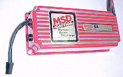
Installation of the MSD 6A spark box on E systems set up for a direct MSD trigger from the ECU is as follows:
Heavy black- Battery negative
Heavy red- Battery Positive
Black- Coil negative
Orange- Coil positive
Red- Switched +12 volts
White- SDS blue
Green/violet- Not connected
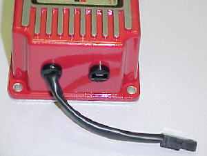
Tachometers can usually be connected to the tach port as seen above (right). Green/purple wires (left) are not used and must NOT be connected to the distributor.
Strange Misses
A couple of things which you can check if you encounter random misses: On distributor equipped engines, be sure to check rotor to cap terminal phasing. Take half of your total timing and position the crankshaft at this figure (about 20 degrees BTDC), line up the rotor with the cap terminal. This will ensure the least posibble gap within the operating range.
Excessive spark plug gap has been found to affect certain engines, especially if you are getting gibberish in the programmer LCD. Try closing the plug gap back to .030.
Other causes for misses may be Hall sensor wires too close to ignition leads, MSD too close to the ECU and using ignition leads with insufficient supression qualities. Solid core, Taylor and Nology are NOT recommended.
Hall Sensor Alignment
Hall sensor to magnet alignment is critical. If your engine idles fine but encounters a severe miss at a certain rpm every time, there is a good chance that the Hall sensor and magnets are not aligned well enough. Even if they register SEEN when the crank is turned by hand, they may be on the fringe and might be missed at higher rpm. You can check Gauge 1 mode, watching rpm as you rev the engine up to the miss point. If the rpm reading suddenly halves or changes radically at that point, alignment is the problem. If the sensor is properly aligned, you should be able to turn the crank at least 3 degrees before the window changes to NOT SEEN. If you only can turn the crank 1 degree before it goes NOT SEEN, you are on the fringe and need to reposition the sensor. The Hall sensor must be mounted to the engine NOT the chassis. Yes, we've actually heard of this being done. On newer systems, (V9 software and up) an RPM ERR code will replace the the RPM reading in Gauge 1 mode if a magnet is missed by the ECU.
E System Testing for MSD Equipped Systems
To test your MSD 6A/6AL for proper function, hook up the box to the coil as shown in the MSD instructions. Place the coil discharge wire about 1/4 inch away from ground. Power up the ignition and momentarily touch the white points trigger wire to chassis ground. When you do this, you should see a spark jump between the coil wire and ground. This verifies MSD function.
To test that the SDS ECU is okay, get an injector and connect one terminal to +12 volts and the other terminal to the blue wire on the main SDS harness. Power up the ECU. Turn the crankshaft by hand until a magnet passes the Hall sensor. If the ignition trigger is working, you should hear the injector click.
Fuel Contamination
We have had 3 reports of customers experiencing serious tuning difficulties with their SDS units. All 3 had previously had their engines running well, then after some time, the engines were running poorly and no amount of tuning seemed to help. In two cases, serious amounts of water (several gallons) was found in the fuel. In the third case, the car had sat for about 6 months and the fuel was found to be highly oxidized or contaminated (it was brown and murky). Draining the tanks and fresh fuel solved all of these problems. Yet another case of "it's not the computer syndrome". If the engine ran right before then it suddenly doesn't, check those grounds, fuel pump delivery and pressure, spark plugs and wires, cam timing and take a fuel sample. Water will sit on the bottom of a glass jar. A fourth case found scum inside the tank and covering part of the fuel pump screen. This car exhibited severe hitching from time to time and intermittent engine shutdown. Octane booster and methanol had been added for track sessions. These compounds may have reacted to form this scum in the fuel tank.
F Coil Testing
Some people have reported difficulty in understanding how to test F coils for spark. Below are 2 photos showing simple setups to test for spark. Use the procedure in the F manuals. We hope that this clarifies things for readers.
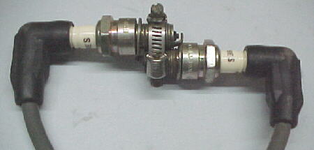
Clamp two plugs together from each coil with a hose clamp
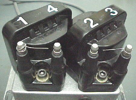
Wrap a short piece of wire around one coil terminal on each coil and leave a 1/4 inch gap
Ignition Wires
Proper operation of the SDS ECU requires the use of radio suppression type ignition leads. SOLID CORE WIRES CANNOT BE USED. Resistance type wires should measure a minimum of 3,000 ohms per foot. We highly recommend MSD Superconductor wires. We don't recommend the use of Taylor or Nology wires with our systems.
Quick Injector Sizing
For quick determination of injector size, multiply flow rate in cc per minute by the number of injectors. Divide this number by 7. This will give the maximum hp possible at 85% duty cycle. Example: 4 x 500cc = 2000. 2000 divided by 7 = 285 hp.
Another formula to figure out maximum power per injector flow rate is:
Injector flow rate in pounds per hr. x the number of injectors, divided by 0.55.
For a quick lookup chart: techffhp.htm